دليل تركيب الطاولة متعددة الكاميرات والطاولة بدون مركز في PhotoRobot
تحتوي الوثائق التالية على تعليمات مفصلة حول تجميع والاستخدام الأول لكاميرا PhotoRobot MultiCam (Pro / Pro XL) مع الطاولة بدون مركز (CL1300 / CL850). تهدف هذه المعلومات إلى دعم عملاء PhotoRobot الذين اشتروا مؤخرا جهاز PhotoRobot. يتضمن الكتاب نظرة عامة على التقنية، مع دليل خطوة بخطوة لتركيب الكاميرا المتعددة مع طاولة PhotoRobot بدون مركز.
مهم: يرجى دائما الرجوع إلى معلومات وتعليمات السلامة الخاصة ب PhotoRobot مع أي وثائق مقدمة خصيصا لجهازك. بالإضافة إلى ذلك، يجب دائما تنفيذ التركيب الأولي لجهاز PhotoRobot بواسطة سلطة معتمدة ل PhotoRobot. الجهات المختصة بتركيب PhotoRobot هي موزع معتمد، أو ممثل الشركة المصنعة نفسها.
ملاحظة: للحصول على نظرة عامة على أجهزة الطاولة بدون مركز ودمجها في استوديو التصوير، يرجى الرجوع إلى دليل المستخدم CL850 - CL1300 Table بدون مركز.
PhotoRobot MultiCam Pro / Pro XL وطاولة بدون مركز
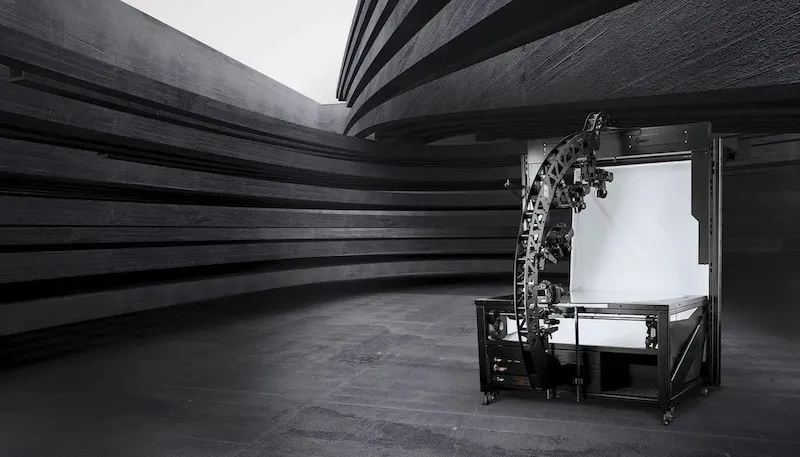
شكرا لك ومهانينا على شرائك لكاميرا PhotoRobot MultiCam وطاولة المركز بدون مركز. جهاز PhotoRobot MultiCam Pro / MultiCam Pro XL هو جهاز متعدد الكاميرات متوافق مع كل من طراز CL1300 وCL850 بدون مركز للطاولات بدون مركز. باعتباره جهازا متعدد الكاميرات، يعمل النظام بالتزامن مع ديناميكيات دوران الطاولة بدون مركز لأتمتة التقاط عدة كاميرات لتصوير المنتجات متعددة الصفوف وثلاثية الأبعاد. يتيح ذلك التقاط منتجات من ارتفاعات متعددة في آن واحد لإنتاج تجارب ثلاثية الأبعاد كاملة، ودورات منتجات ثلاثية الأبعاد، وصور لتوليد نماذج ثلاثية الأبعاد.
1. وصف المنتج - مالتي كام برو / مولتي كام برو XL
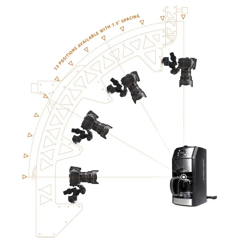
يتوفر مولتي كام في نموذجين: مولتي كام برو، ومالتي كام برو XL الأكبر. الفرق الوحيد هو حجم قوس الكاميرا، حيث يعمل XL كأكبر بين الطرازين. كل من MultiCam Pro و Pro XL متوافقان مع جميع أجهزة تشغيل الأسطوانات الروبوتية PhotoRobot. يتيح الجهاز التقاط 144+ صورة من عدة كاميرات خلال حوالي 20 ثانية. يشمل ذلك التقاط زوايا التسويق والزوايا العليا في نفس الوقت ضمن نطاق دوراني 360 درجة. وفي الوقت نفسه، فإن التحكم الدقيق للغاية في الكاميرا والتقاط الصور مع توفر 13 موقعا للكاميرا يدعم التصوير السريع متعدد الصفوف. تمكن دقة الالتقاط الآلي من المعالجة اللاحقة التلقائية للصور الفردية لتوليد النماذج ثلاثية الأبعاد والدوران.
المكونات والميزات الرئيسية لجهاز MultiCam Pro / Pro XL تشمل:
- التقاط عدة كاميرات متزامن في دوران واحد لجهاز تشغيل الأسطوانات
- قوس الكاميرا متوفر بحجمين (Pro / Pro XL)
- التحكم البرمجي في جميع الكاميرات في نفس الوقت
- دعم 13 وضعية كاميرا بمسافة 7.5°
- تعديل الارتفاع بمساعدة المحرك إلى مركز الأجسام المصورة
- إعداد دقيق وموثوق للكاميرات بفضل صلابة الهيكل العالية
- مجموعة واسعة من الإكسسوارات لرؤوس الحامل الثلاثي مانفروتو
- بوابة MultiCam للاتصال السريع بمحطات عمل PhotoRobot المختلفة
- خيارات الإضاءة لكل من الإضاءة الفلاش والإضاءة المستمرة في الاستوديو
1.1. نظرة عامة على محطة العمل - CL1300 / CL850
يعمل الكاميرا المتعددة مع الطاولة بدون مركز (CL1300 / CL850) كحل عالمي لجهاز تشغيل التصوير الفوتوغرافي ونظام متعدد الكاميرات للتصوير ثلاثي الأبعاد الروبوتي. معا، يتيح الجهازان التصوير الآلي بدون ظل للمنتجات الصغيرة إلى المتوسطة الحجم. يشمل ذلك أشياء ذات خصائص فوتوغرافية مختلفة: منتجات شفافة، لامعة، فاتحة، وداكنة. وفي الوقت نفسه، تحمل لوحة الزجاج الدوارة أشياء تتراوح من حجم القرط إلى الأمتعة، مع خلفية منتشرة تتيح إضاءة متساوية للأجسام من جميع الجهات أثناء التصوير. وبالتالي، يمكن لكل كاميرا تلتقط من الكاميرا المتعددة إنشاء صور عالية الجودة تلقائيا على خلفية بيضاء نقية، بما في ذلك زوايا التسويق والزوايا العلوية في نفس الوقت. وفي الوقت نفسه، يضمن ذلك أتمتة سريعة وعالية الكفاءة في معالجة الصور ونشرها.
1.2. مكونات الجدول متعدد الكاميرا والمراكز
المكونات الرئيسية لكاميرا متعددة مع تركيب طاولة بدون مركز تشمل أجزاء كلا الجهازين ووحدات التحكم الخاصة بهما.
- مجموعة الطاولة بدون مركز أساسية (جسم الجهاز، الإطار، الصدغ)
- رف HD بدون مركز مع وحدات تحكم وراوتر
- وحدة التحكم G6، صندوق الليزر، صندوق المفتاح، وصندوق السينكرو
- توجيه الكابلات الداخلية عبر الهيكل الأيسر واليمنى
- وحدة تحكم حاملات خلفية الطاولة بدون مركز
- توصيل الليزر لمحطات العمل وحوامل مصابيح اليدوية
- لوحة طاولة بدون مركز (1300 مم / 850 مم)
- تجميع خلفية الطاولة بدون مركز
- بوابة MultiCam للإعداد السريع في محطة العمل
- قوس الكاميرا المتعددة وتركيب الكاميرا، وتوصيلات الكابلات
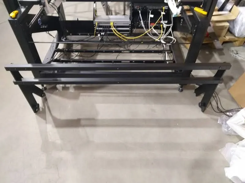
2. تجميع الطقم الأساسي لكاميرا متعددة مع CL1300 / CL850
يبدأ تجميع الكاميرا المتعددة مع CL1300 / CL850 من مجموعة الطاولة الأساسية لجهاز الطاولة بدون مركز. المجموعة الأساسية تمثل جسم (الإطار) للطاولة بدون مركز.
2.1. بناء مجموعة CL1300 / CL850 الأساسية
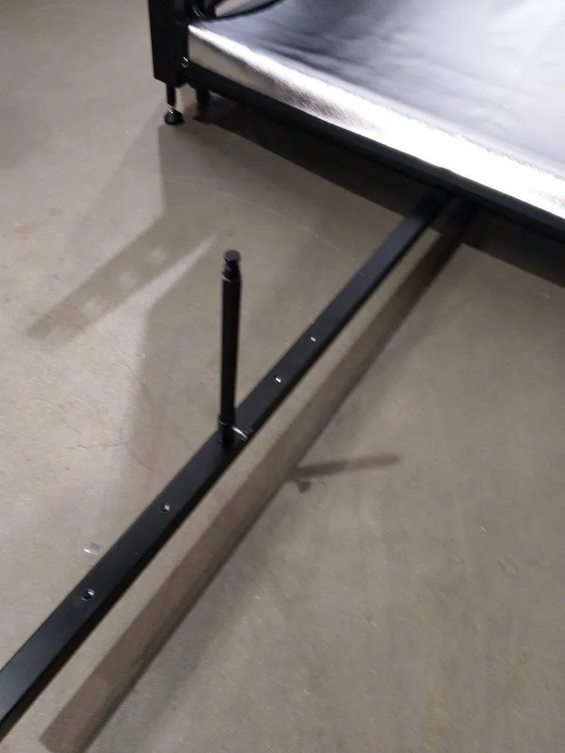
2.1.1. ضع مجموعة الطاولة الأساسية بدون مركز على سطح مستو، مع التأكد من استقرارها بشكل متساو على الأرض.
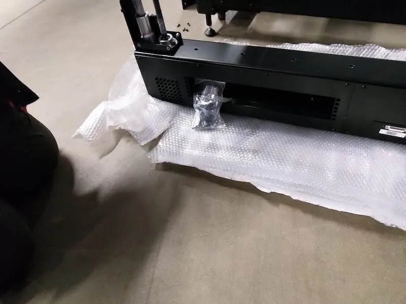
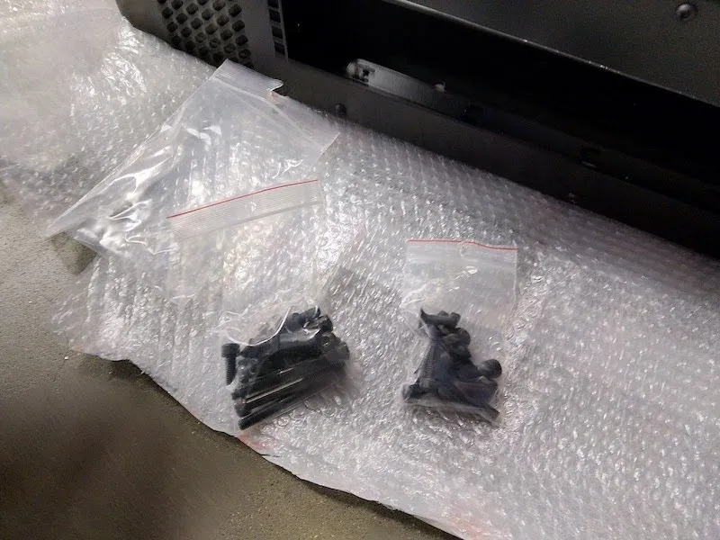
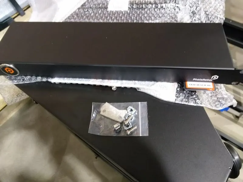
2.1.2. حدد موقع الصندوق الكرتوني المعلم الذي يحتوي على 20 حلقة مطاطية، و10 دبابيس، و5 مقبس، و4 أقدام مقطوعة.
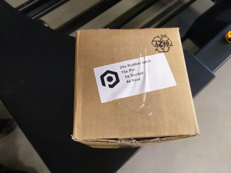
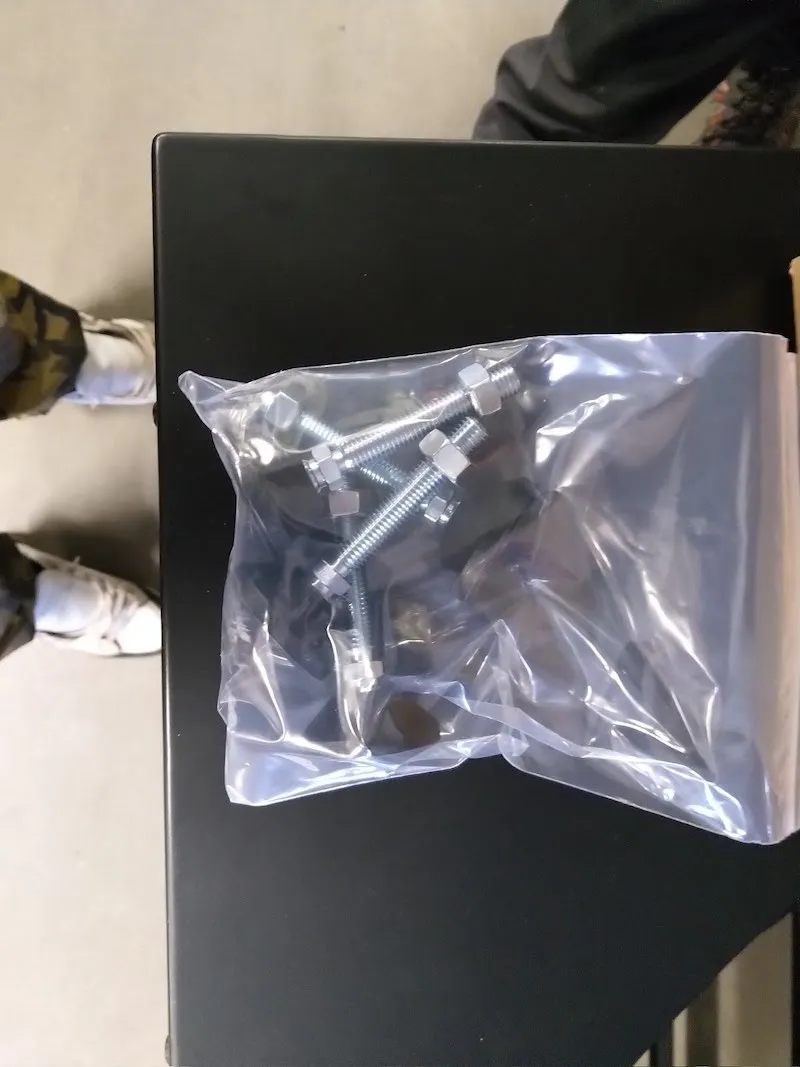
2.1.3. قم بفك الصندوق وخذ الكيس البلاستيكي الذي يحتوي على 4 أقدام مع دبابيس ومقابس.
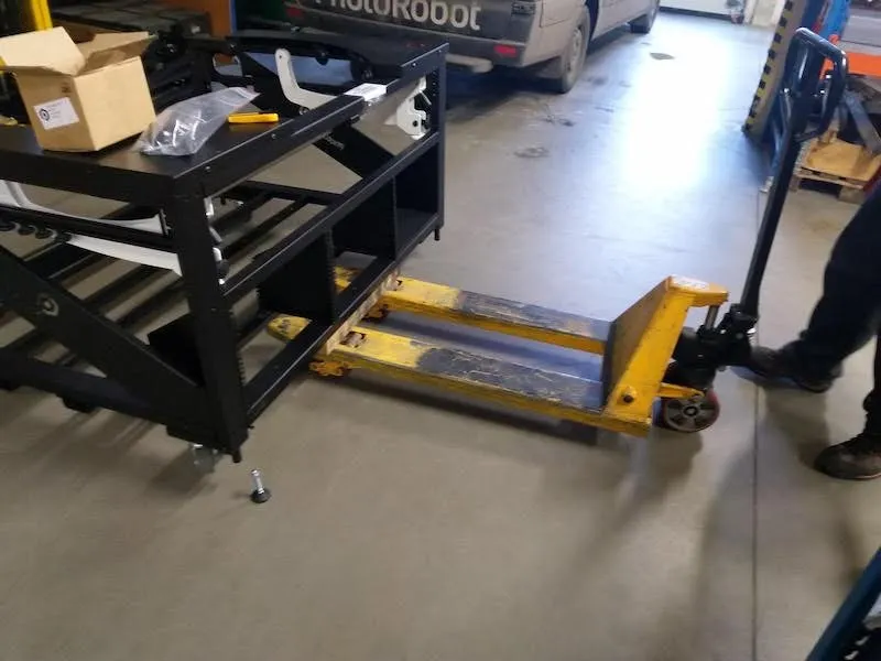
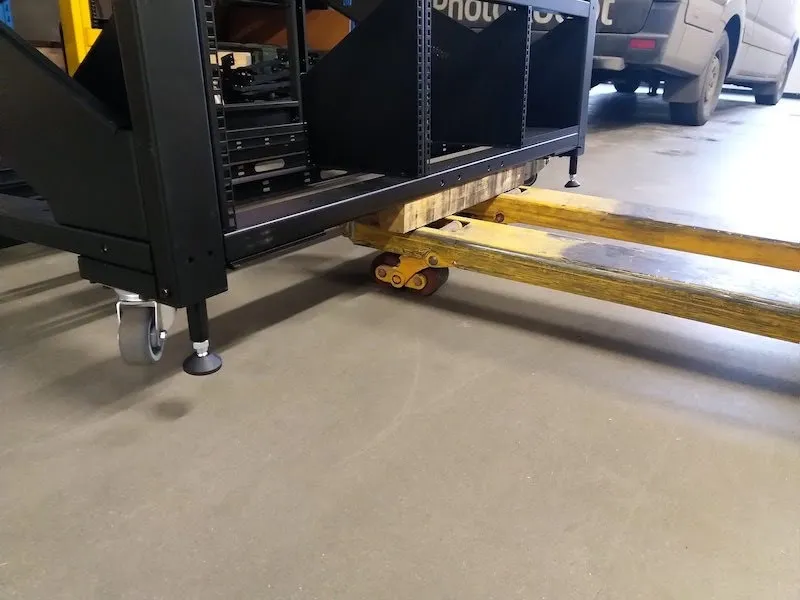
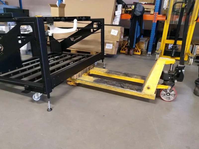
2.1.4. استخدم رافعة شوكية أو جهاز رفع مشابه لرفع CL1300 / CL850 فوق الأرض إلى ارتفاع كاف وتثبيت الأربعة أقدام مقلوبا إلى وضعها. ثبت كل قدم × 4 بإحكام وبأقصى ما يمكن داخل إطار الجهاز.
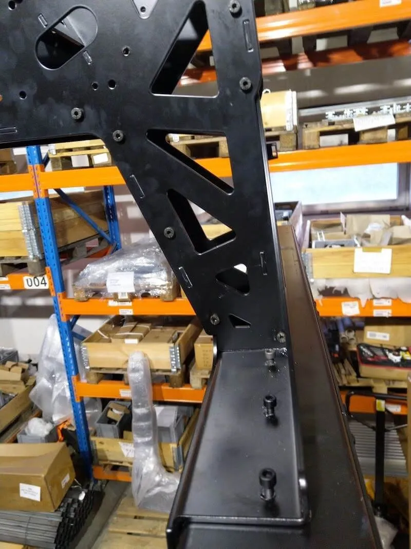
2.2. تجميع المعبدات من النوع H، النوع R
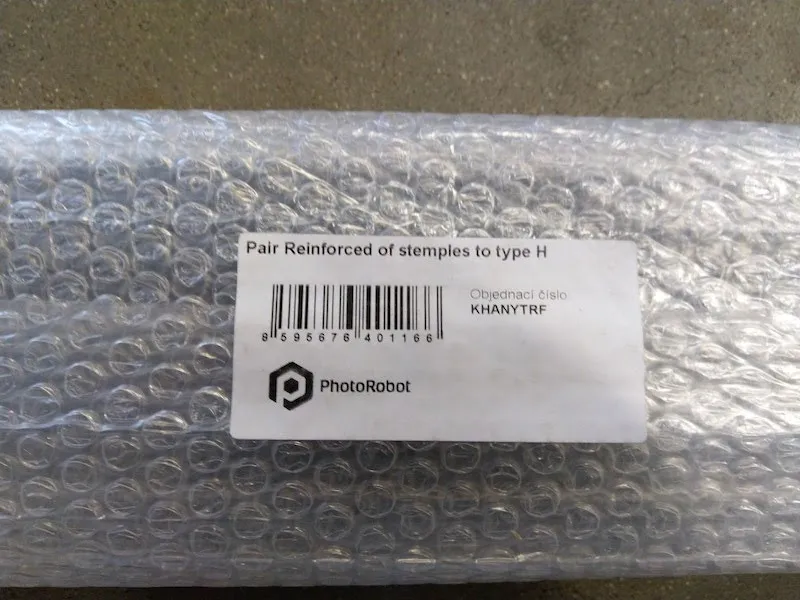
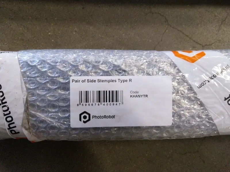
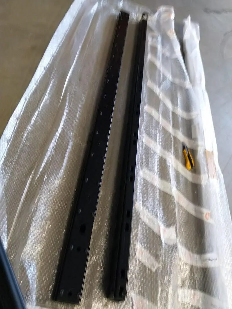
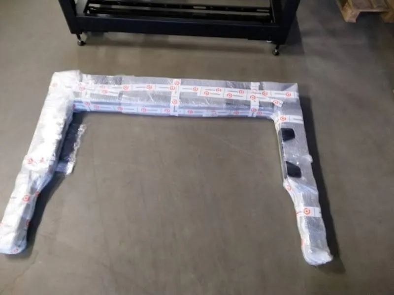
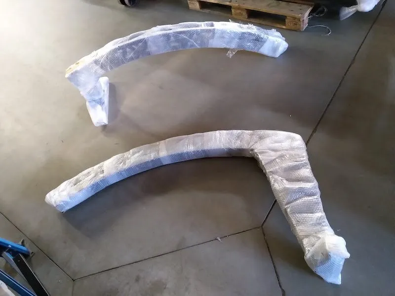
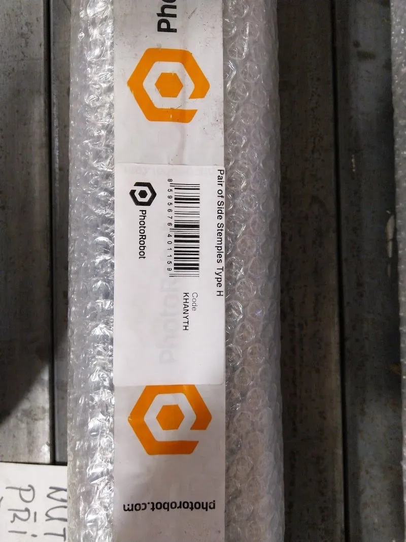
2.2.1. تحديد موقع القوالب الآلية المعبأة في غلاف الفقاعات ومعنون: "القوالب المعززة إلى النوع H" (الرمز: KHANYTRF)، و"القوالب الجانبية النوع R" (الرمز: KHANYTR).
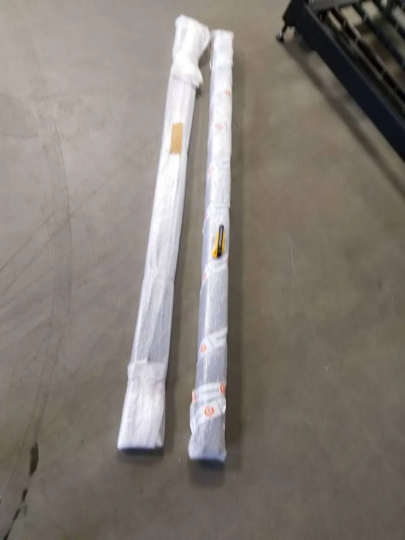
2.2.2. إزالة مجموعتي الصدغ من التغليف.
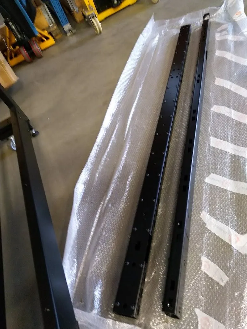
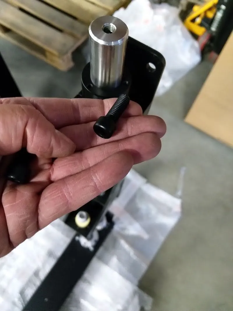
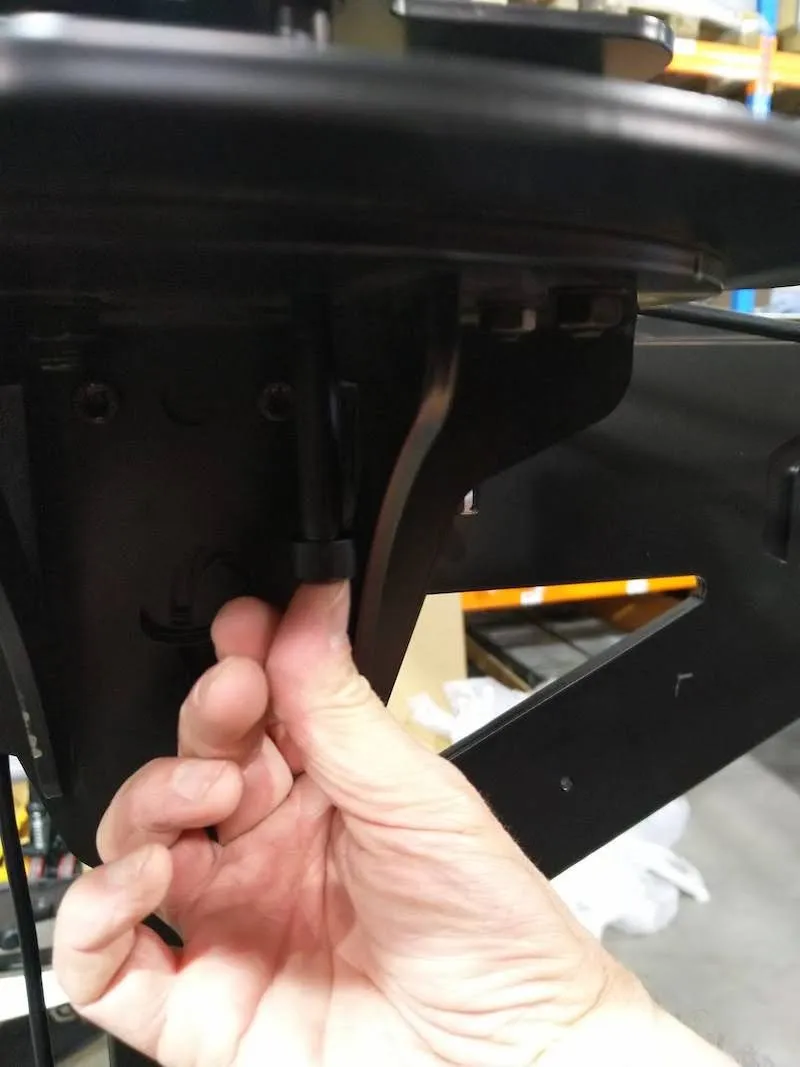
2.2.3. حدد موقع البراغي الأربعة المزودة بالغسالات السميكة على جانبي الطاولة بدون مركز، وفك كل من البراغي الأربعة لفكها.
2.2.4. بعد ذلك، ثبت الصدغ الجانبية غير المدعمة (النوع R) على جانبي الطاولة بدون مركز.
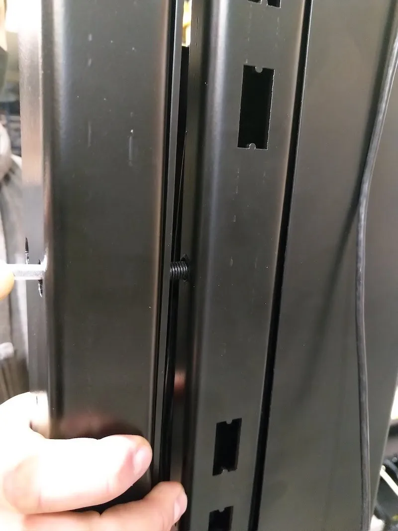
2.2.5. لاحظ المساحات المستطيلة الكبيرة المفتوحة في الصغار. هذه المناطق هي ميزة تصميم لوضع الأسلاك في أسفل الصدغ بجانب براغي التثبيت باستخدام غسالات سميكة.
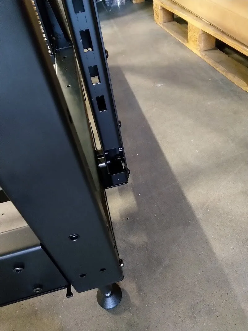
2.2.6. أيضا انتبه إلى الثقبين المستطيلين في أعلى الصدغ من الجانب الخلفي للطاولة بدون مركز.
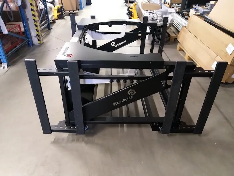
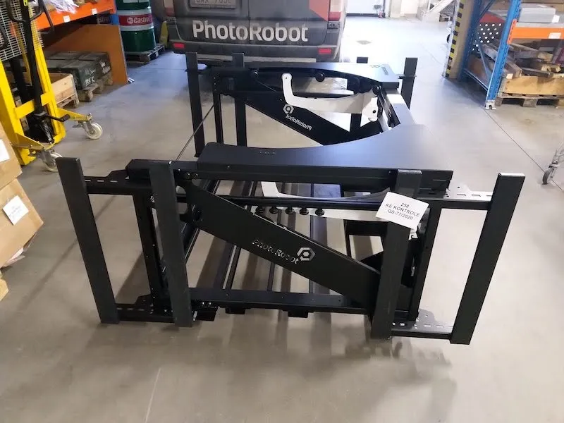
2.2.7. بعد البناء، يعمل الطقم الأساسي كجسم لإطار الآلة، مع صمد على الجانبين وأربعة أقدام في الأسفل.
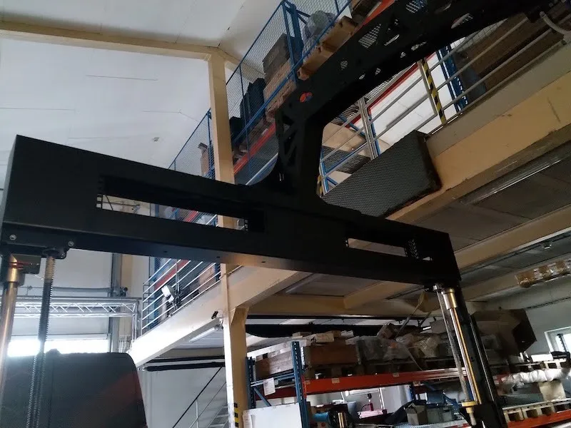
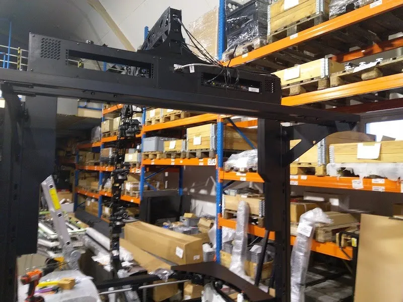
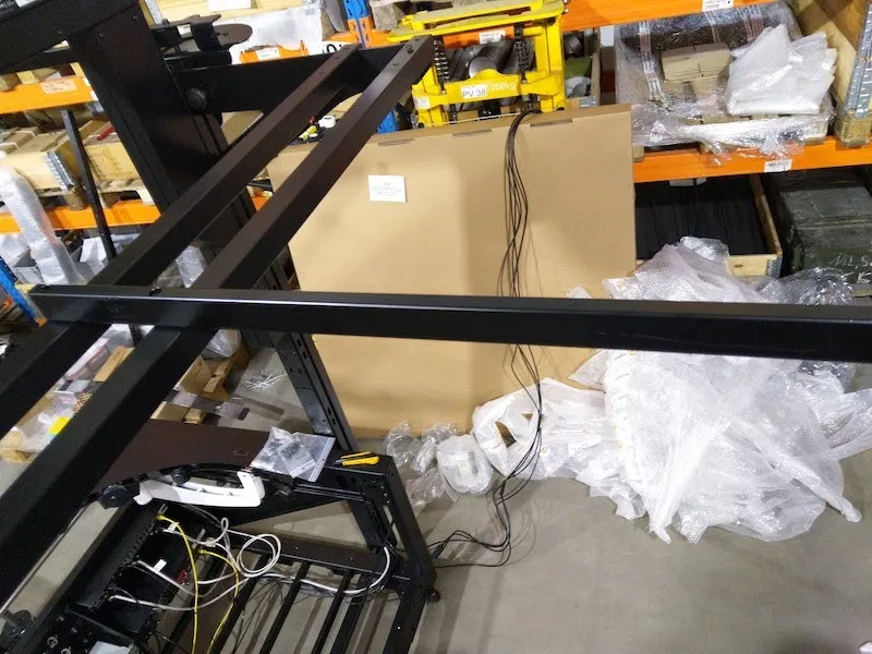
2.3. تجميع بوابة الكاميرا المتعددة
2.3.1. بعد ذلك، حدد الجزء الملفوف بالفقاعات المسمى بوابة الكاميرا المتعددة لجدول 1655 (رمز: KHMCP1655).
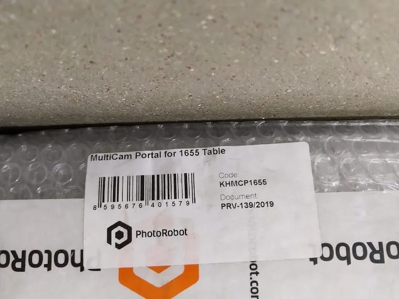
2.3.2. قم بفك بوابة الكاميرا المتعددة وإزالة الأغطية عن أغطية القضيب شبه المنحرف على جانبي البوابة.
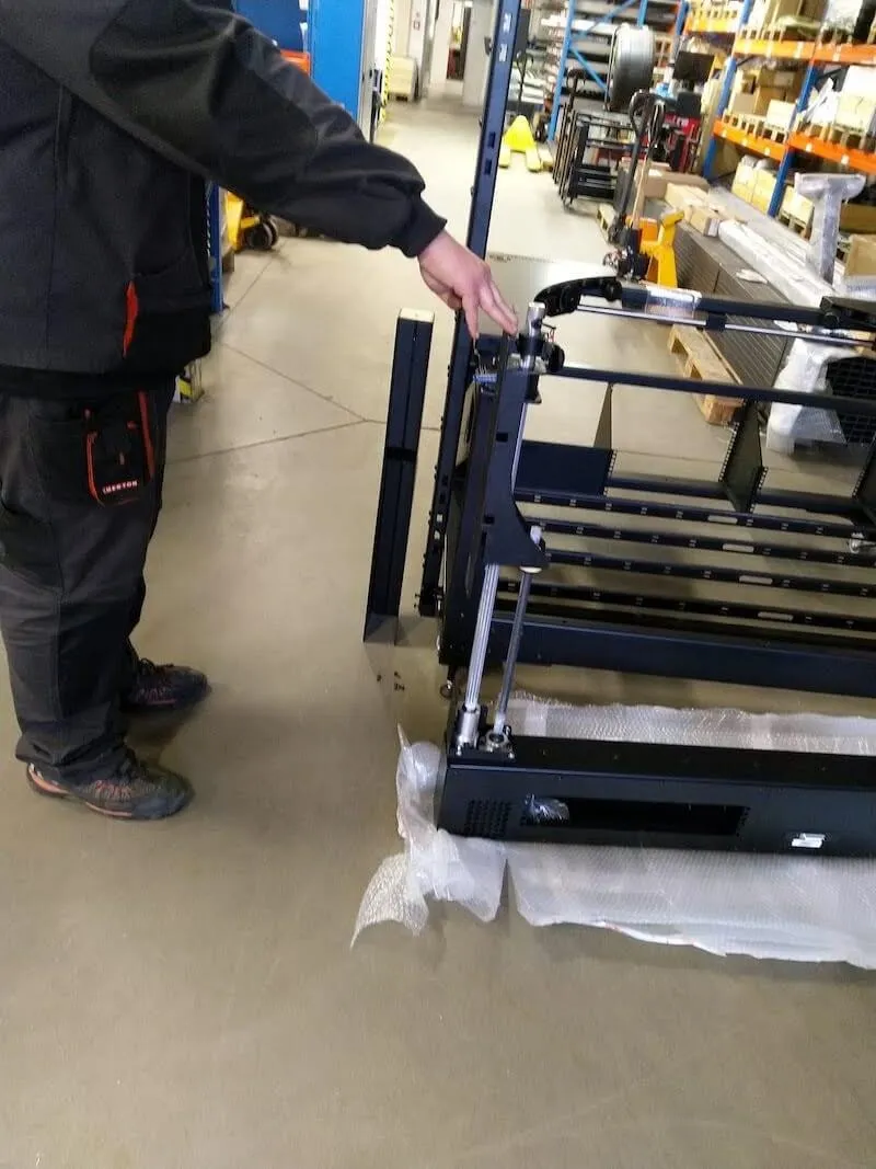
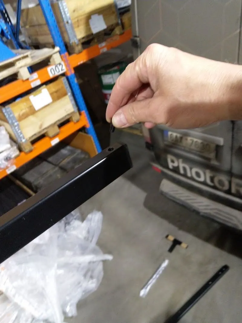
2.3.3. تحديد موقع الأكياس البلاستيكية التي تحتوي على براغي البوابة.
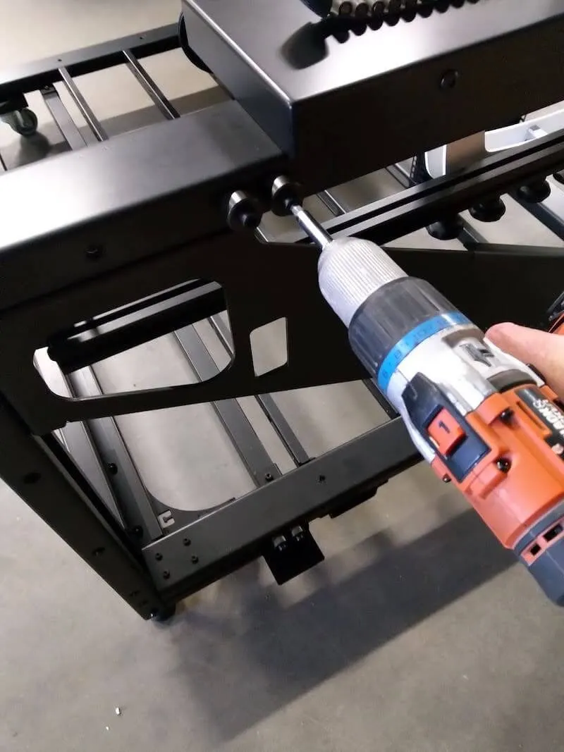
2.3.4. جهز براغيين لتثبيت البوابة في البوابة.
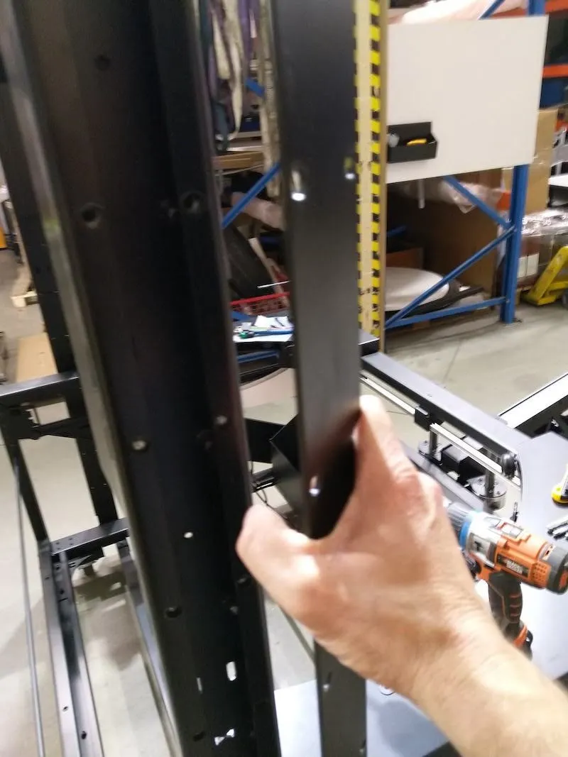
2.3.5. توصيل جانب واحد من البوابة، مع تثبيت برغي واحد فقط للقيام بذلك.
2.3.6. توصيل الجانب الآخر من البوابة، باستخدام مسمار واحد فقط لكل جانب.
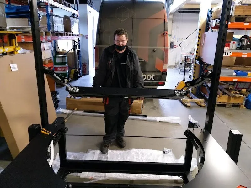
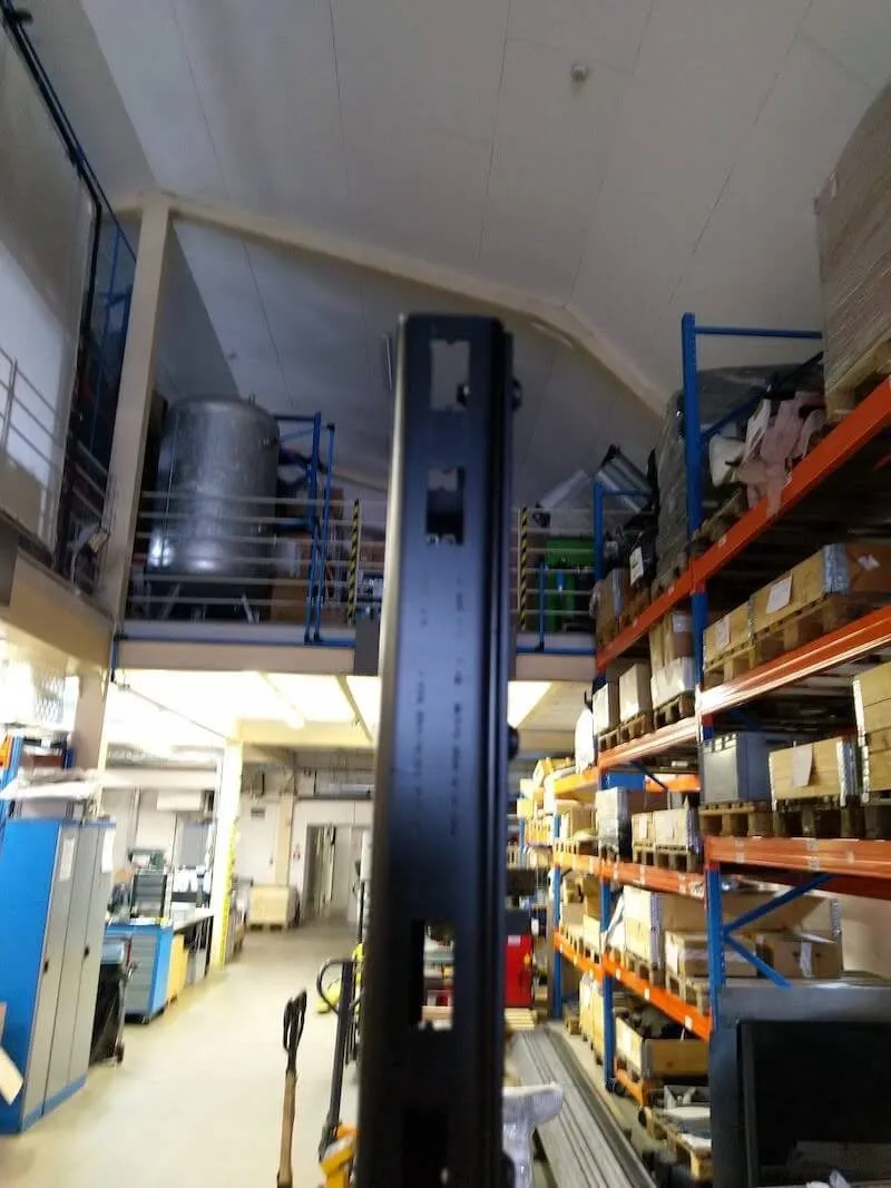
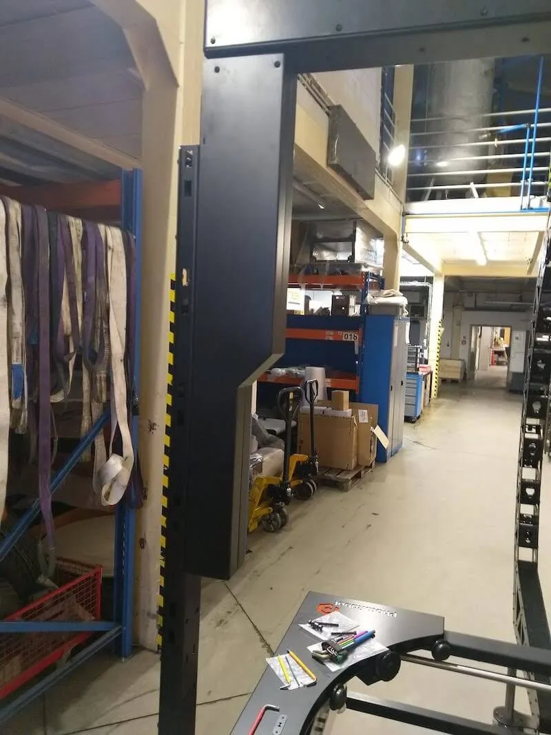
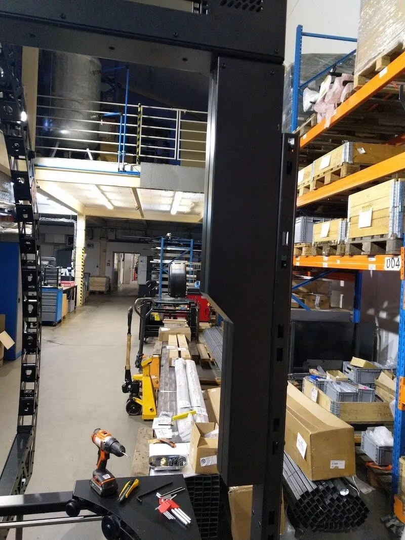
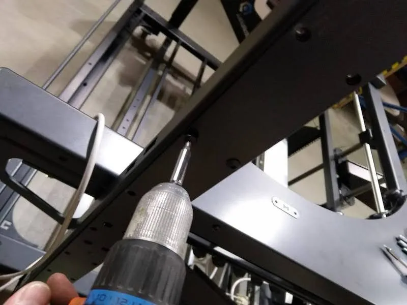
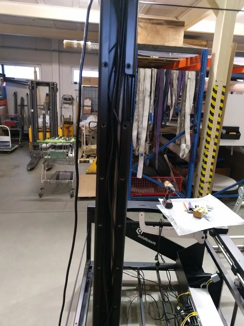
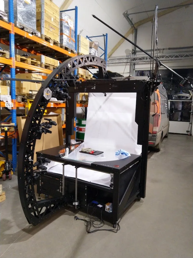
2.3.7. ارفع البوابة إلى وضع عمودي، ثم شد البراغي الثلاثة المتبقية على كل جانب.
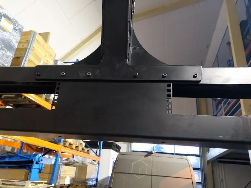
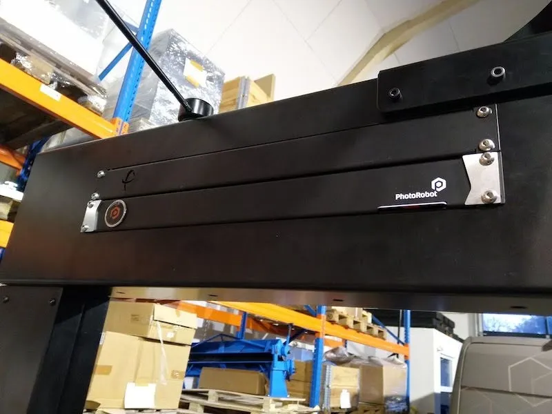
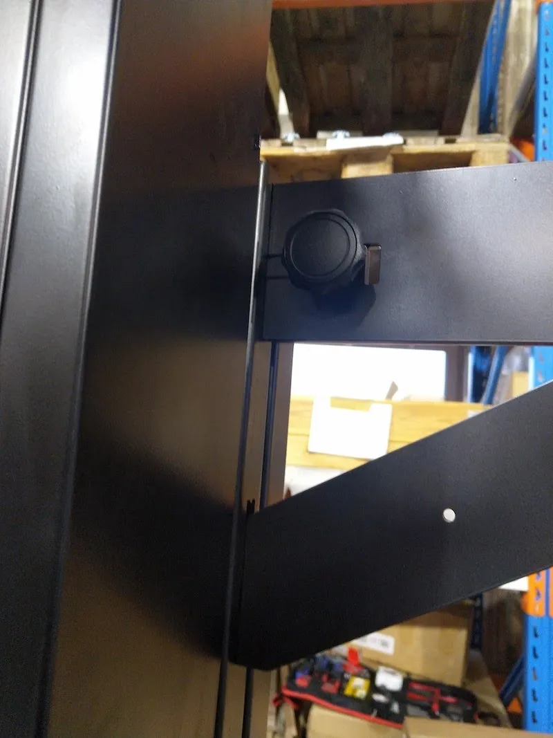
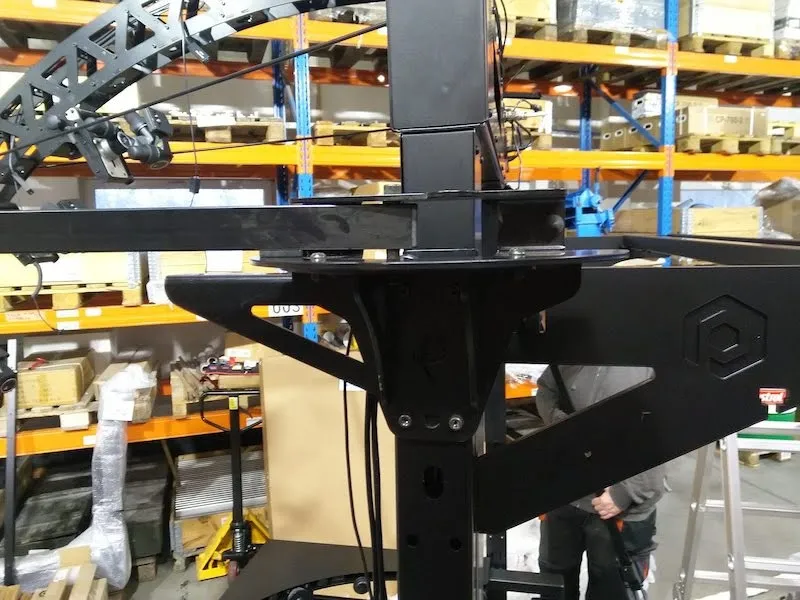
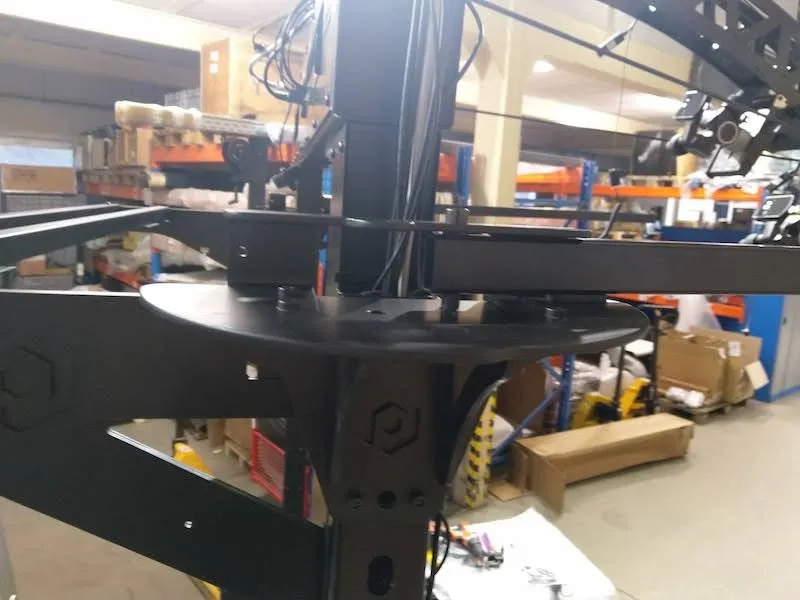
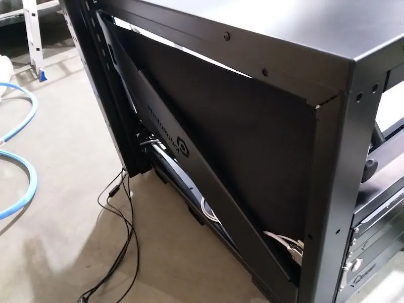
2.3.8. بعد التأكد من تثبيت جميع البراغي بإحكام، يكون تركيب بوابة الكاميرا المتعددة جاهزا ويجب أن يظهر كما هو في الصورة التالية.
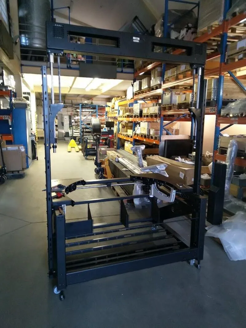
2.3.9. استبدل أغطية القضبان شبه المنحرف وتثبيتها في مكانها.
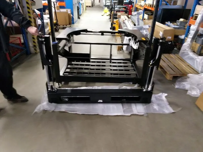
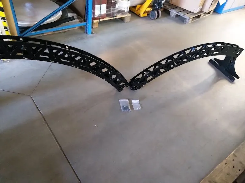
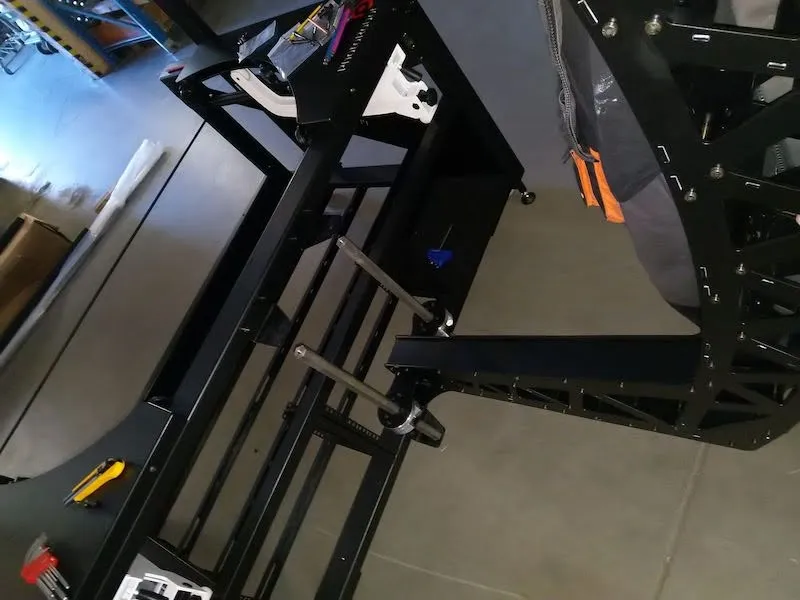
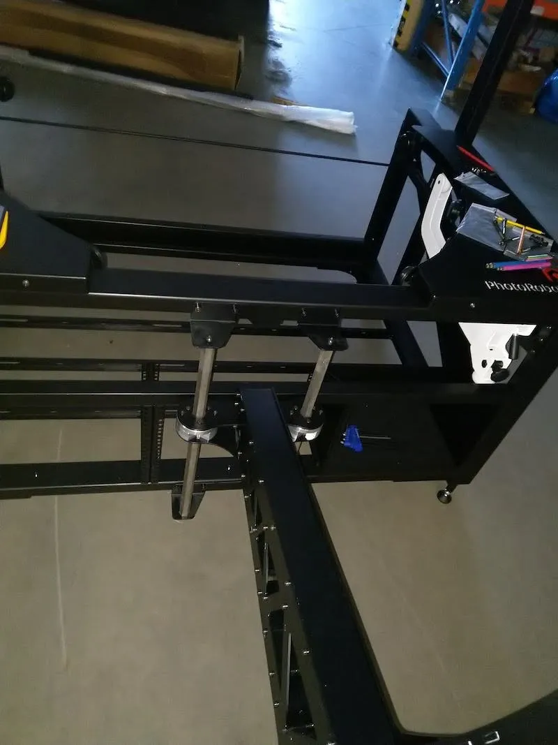
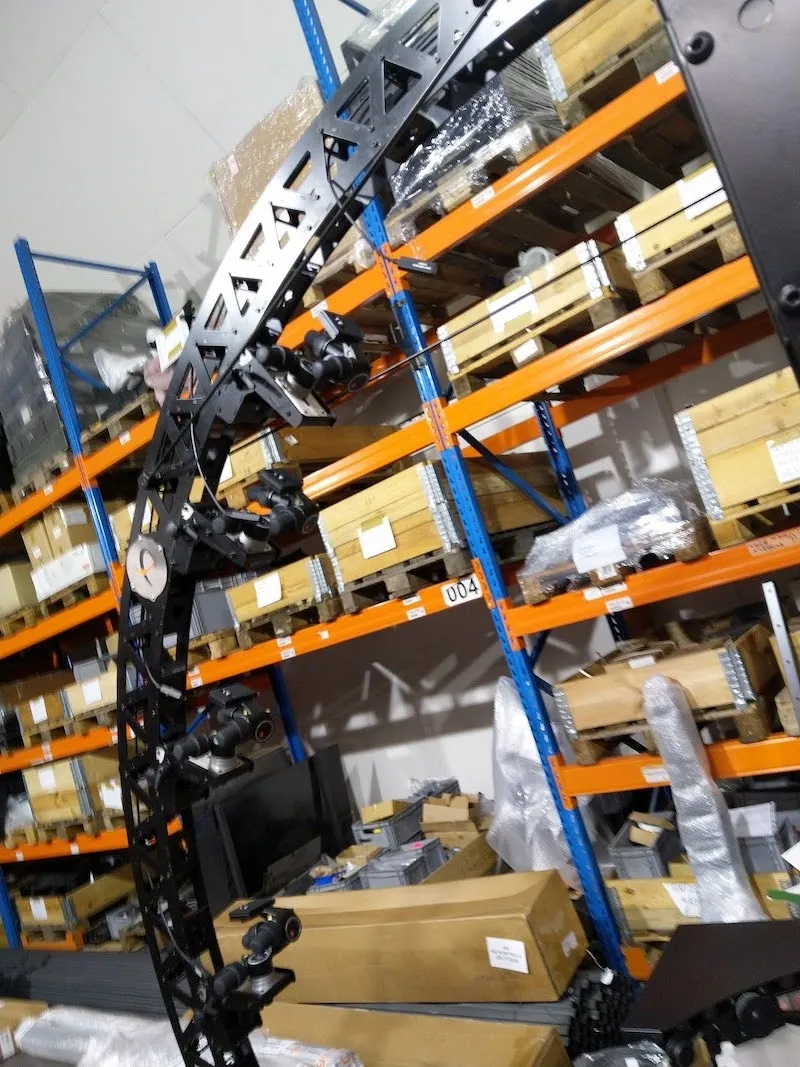
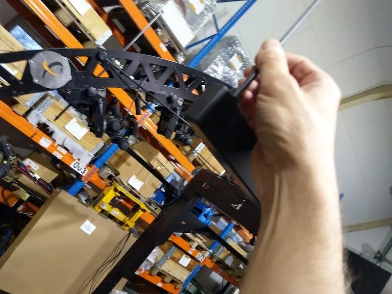
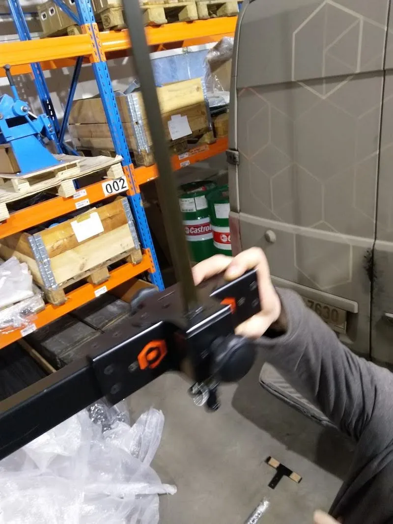
2.4. مجموعة قوس الكاميرا المتعددة
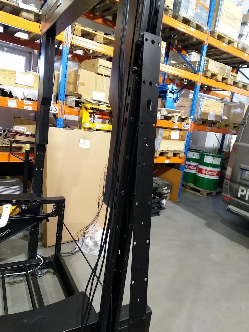
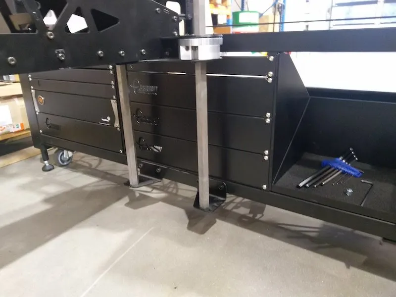
2.4.1. بعد تجميع بوابة MultiCam، الخطوة التالية هي تجميع قوس MultiCam. للقيام بذلك، هناك حاملي قوس يثبتان على الطاولة بدون مركز.
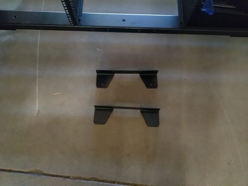
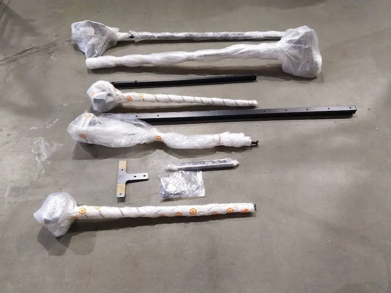
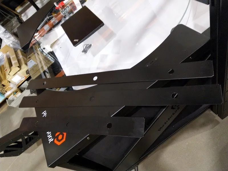
2.4.2. تحديد موقع وفك حوامل الأقواس من غلاف الفقاعات الواقية.
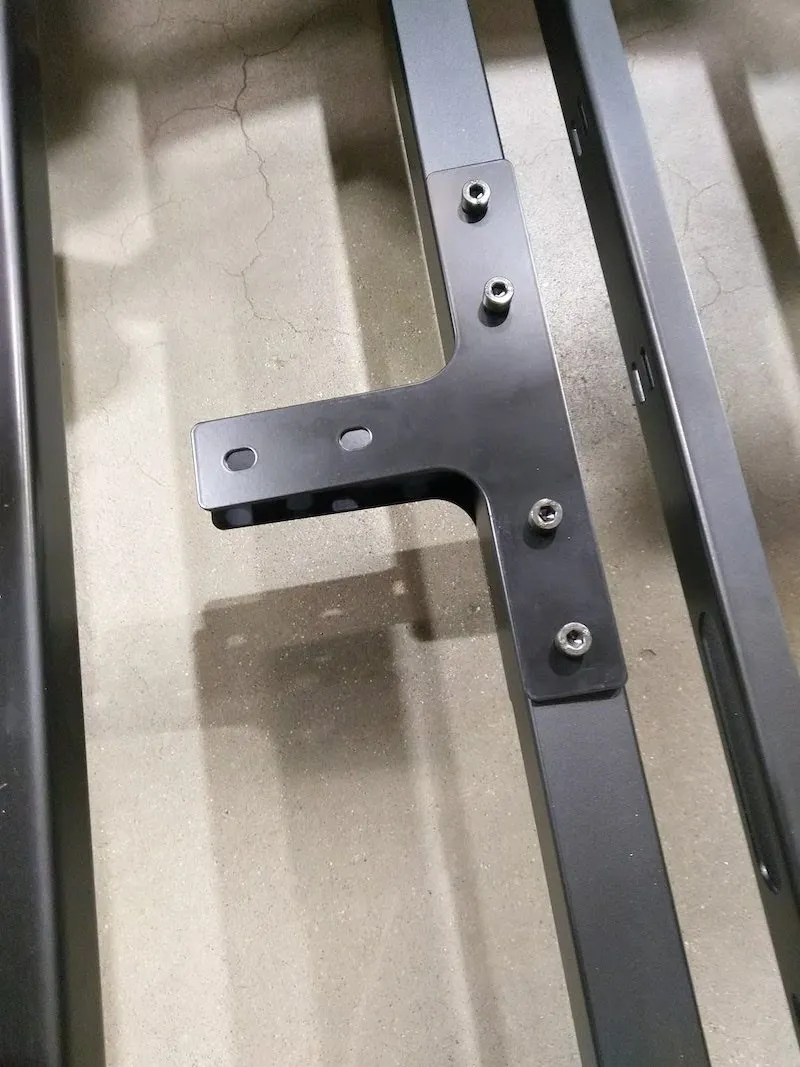
2.4.3. قم بفك حوامل القوس ذات الاثنين باستخدام البراغي، واستعد لربط حوامل القوس معا بوضعها بجانب بعضها كما في الصور التالية.
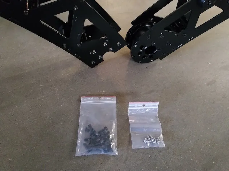
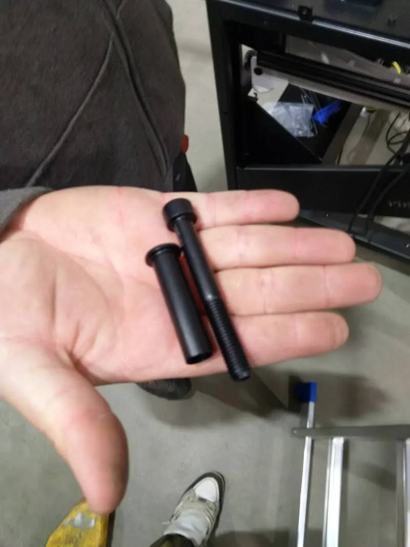
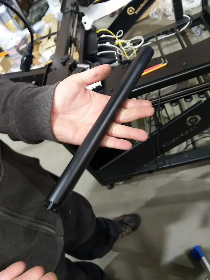
2.4.4. بعد ذلك، حدد القضيبين السداسيين مع شريط لاصق يثبتهما معا، وقم بإزالة الشريط حول القضبان.
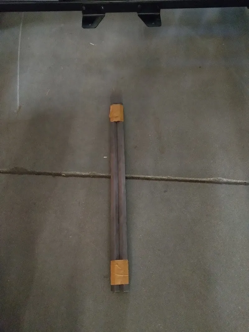
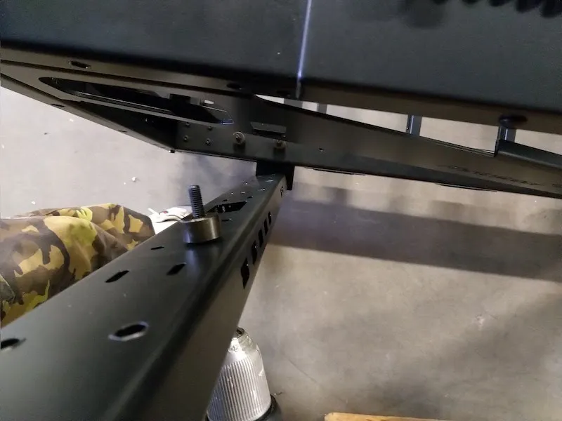
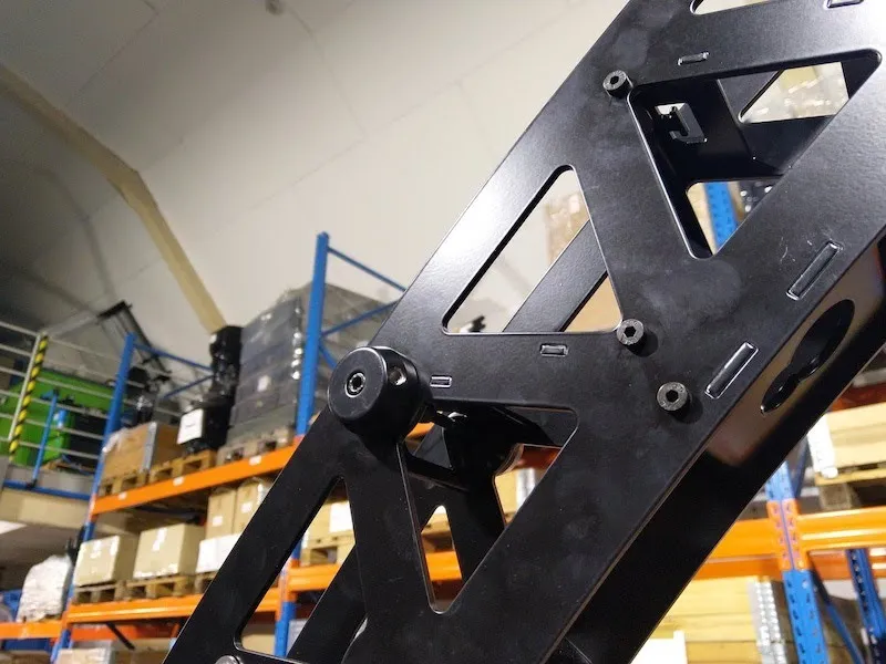
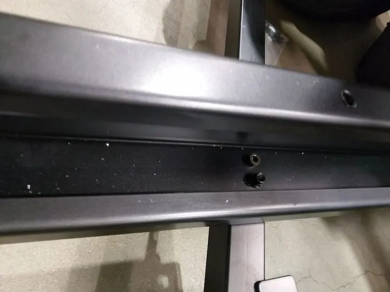
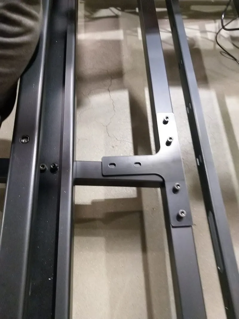
2.4.5. ربط قضيبان توجيه سداسيتين بشكل غير محكم في أسفل حامل القوس.
2.4.6. وضع أحد الأقواس على قضبان التوجيه السداسية.
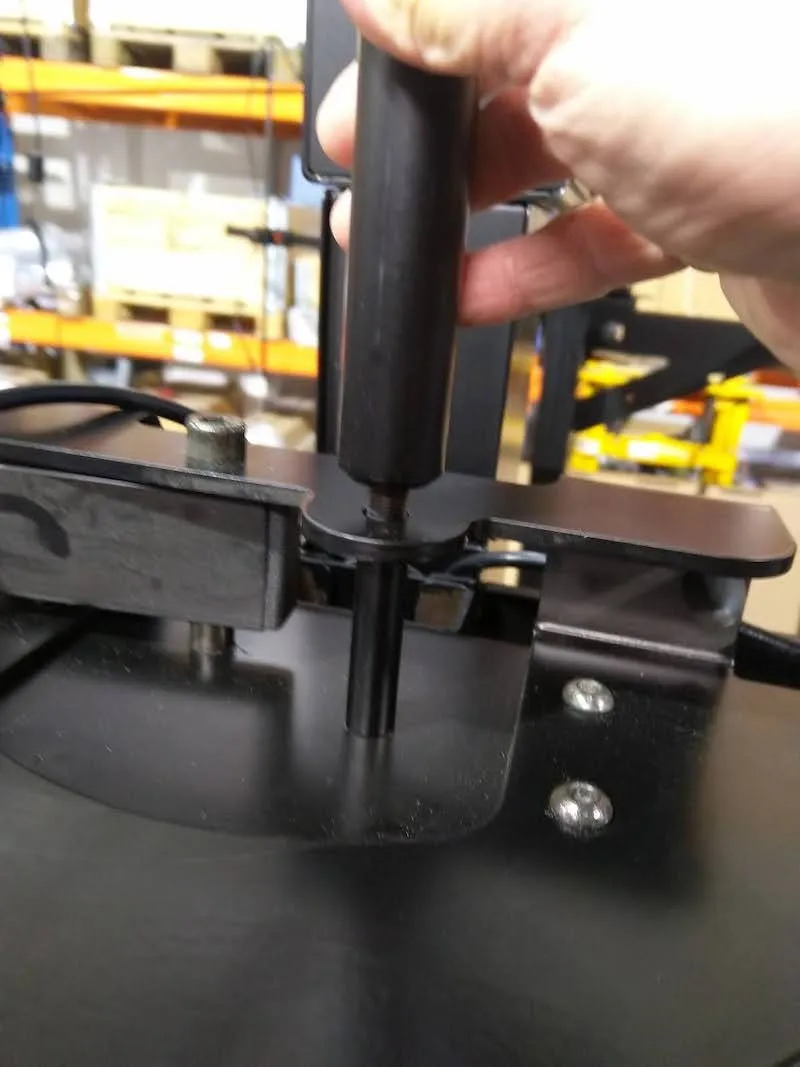
2.4.7. تثبيت الأجزاء العلوية من قضبان التوجيه السداسية على حامل القوس العلوي، ثم تثبيت البراغي السفلية.
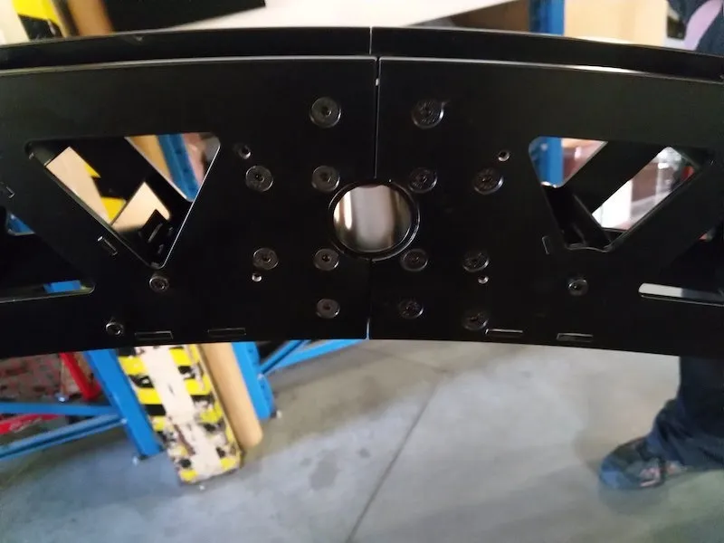
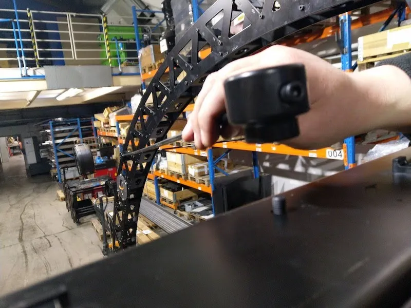
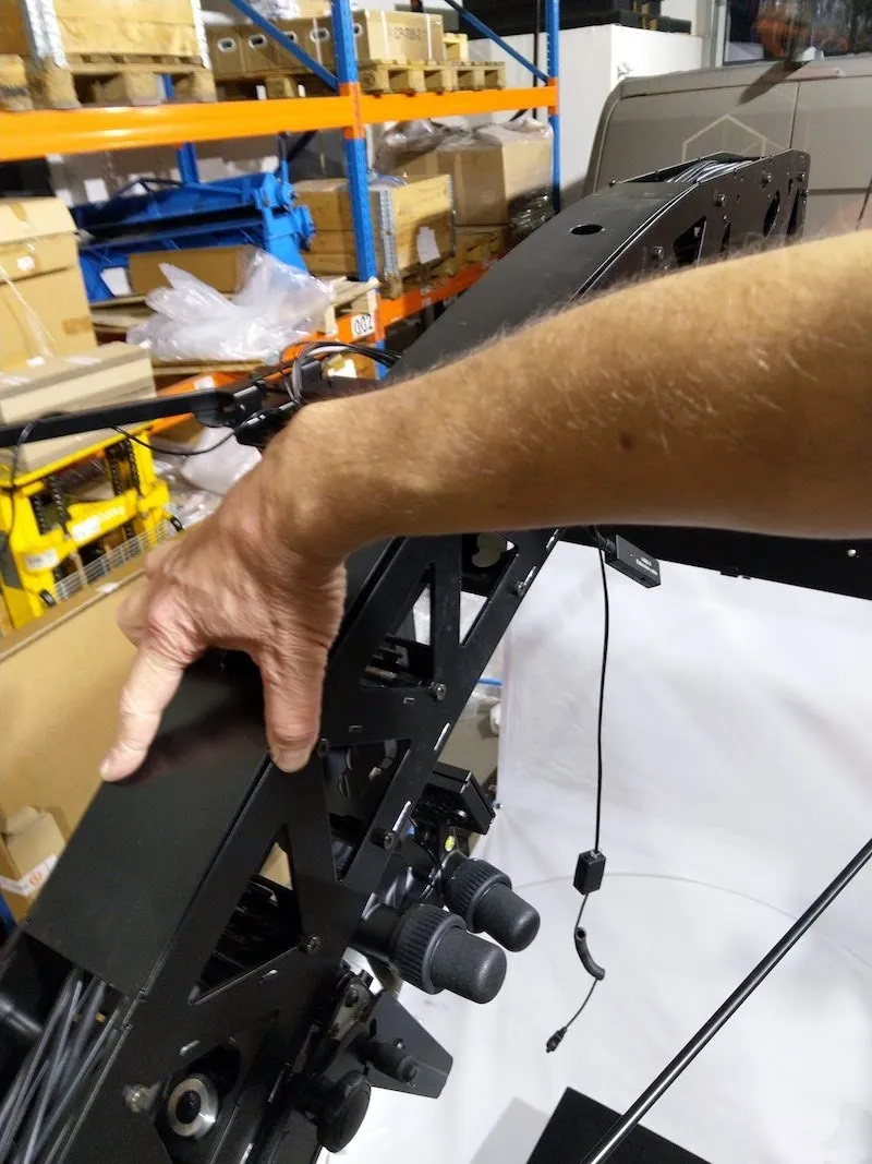
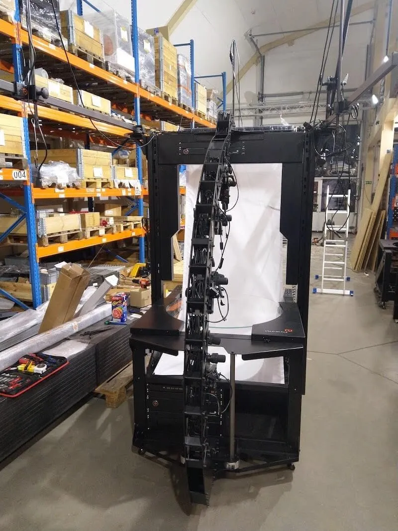
2.4.8. اضغط لوضع الجزء العلوي من القوس على البوابة، وأدخل 6 براغي علوية في الخيوط.
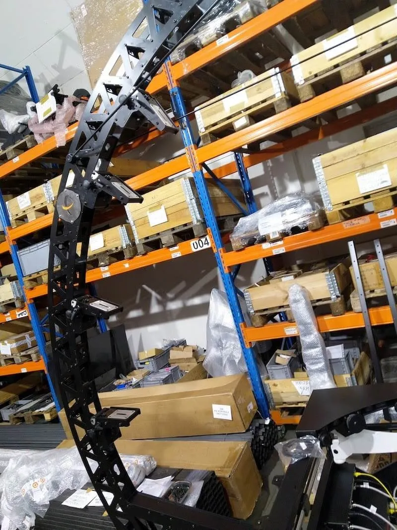
2.4.9. أدخل 6 براغي في الجزء الأمامي من القوس، ثم ثبت جميع البراغي ال12 التي تثبت القوس على البوابة.
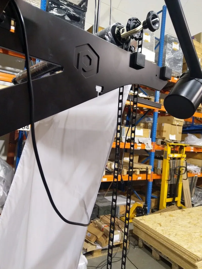
2.4.10. بعد تثبيت الجزء الأمامي من المقدمة على البوابة، ثبت شعار PhotoRobot بإحكام على مقدمة MultiCam.
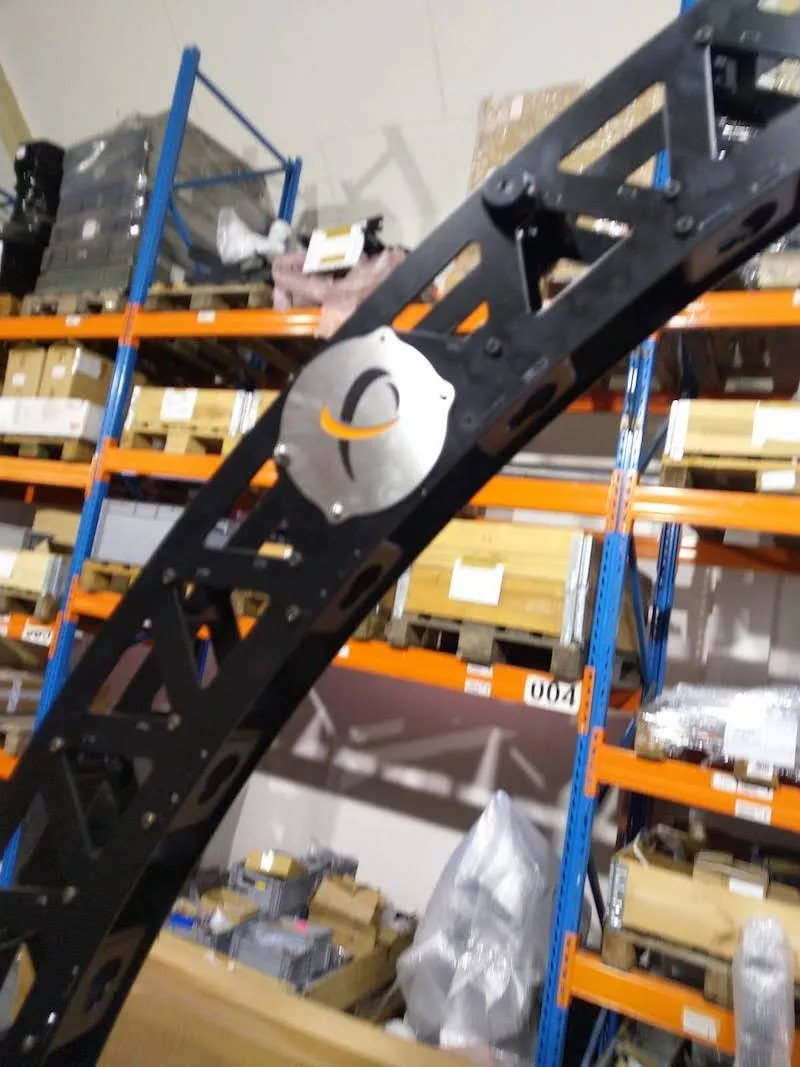
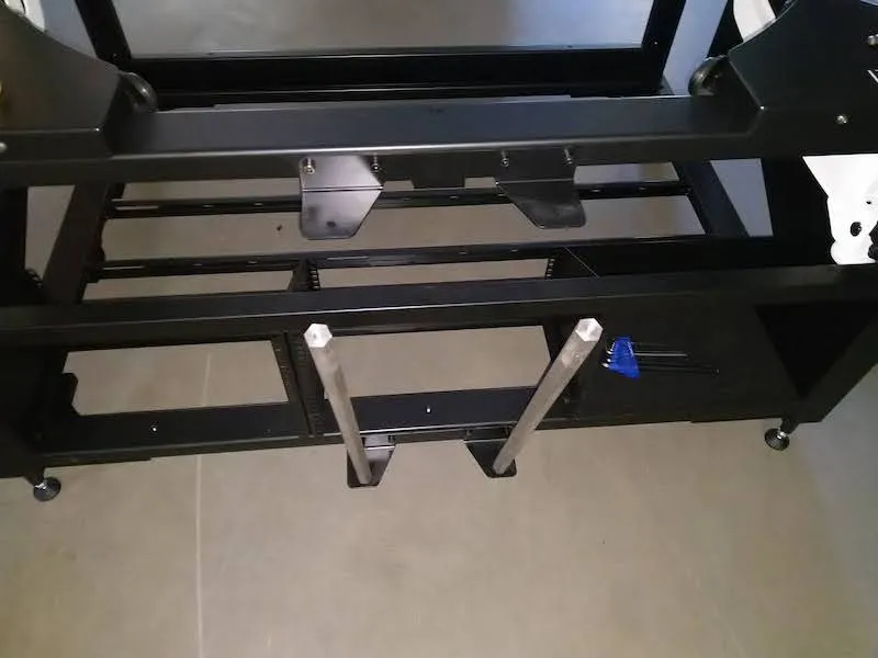
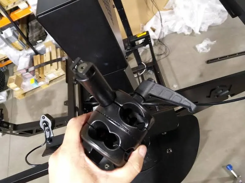
2.4.11. بعد ذلك، قم بتركيب قضيبي القوس المتمركزين على القوس كما في الأمثلة التالية في الصور.
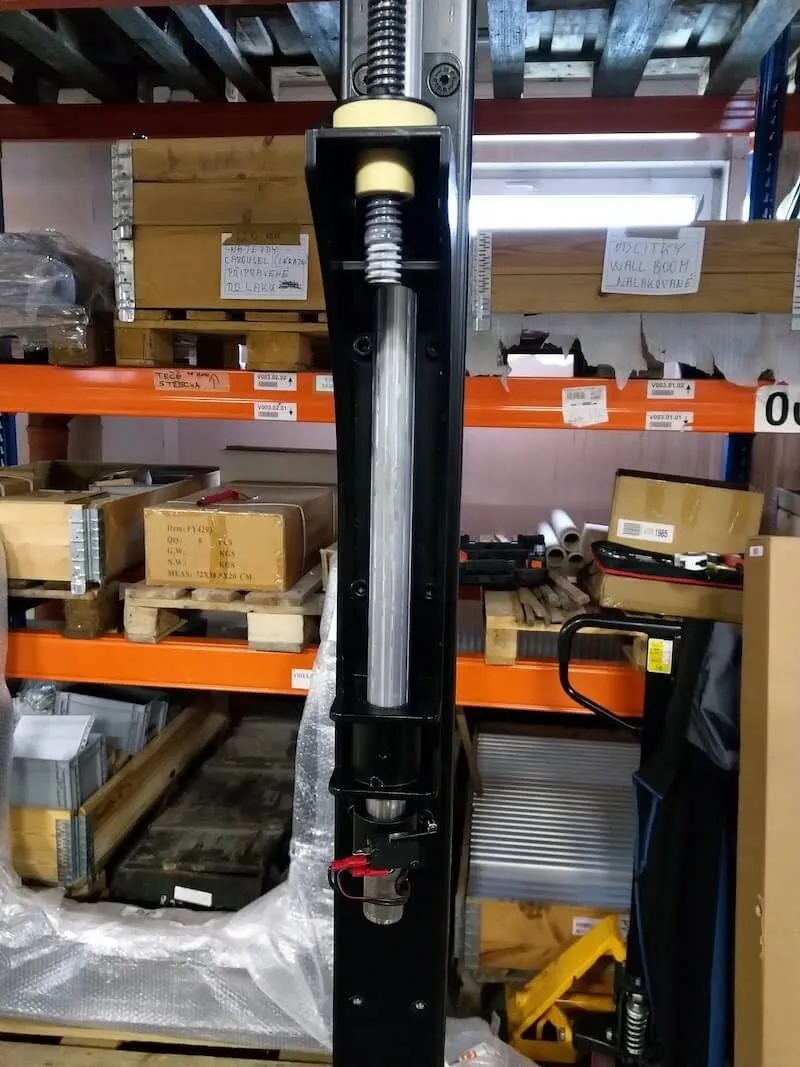
2.5 تثبيت SynchroBox مع MultiCam و CL1300 / CL850
عند اكتمال تجميع قوس MultiCam، حدد موقع PhotoRobot SynchroBox وحامل أعمى للتركيب. PhotoRobot SynchroBox هو مركز متعدد الكاميرات يقوم بمزامنة غالق الكاميرا لكاميرتين أو أكثر. قم بتثبيت SynchroBox والرف الضيق في بوابة MultiCam.
ملاحظة: للحصول على تعليمات تفصيلية حول تكوين وإعداد SynchroBox، يرجى الرجوع إلى دليل المستخدم لإعداد PhotoRobot - SynchroBox.
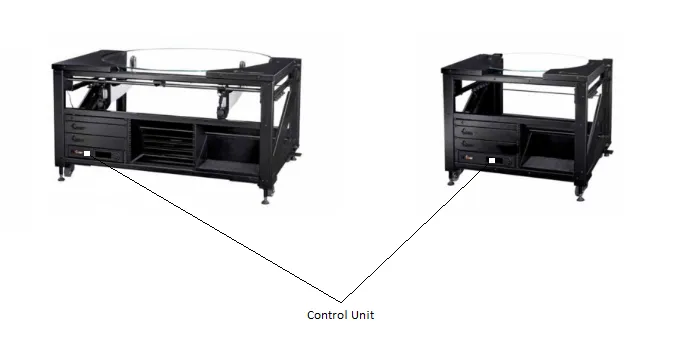
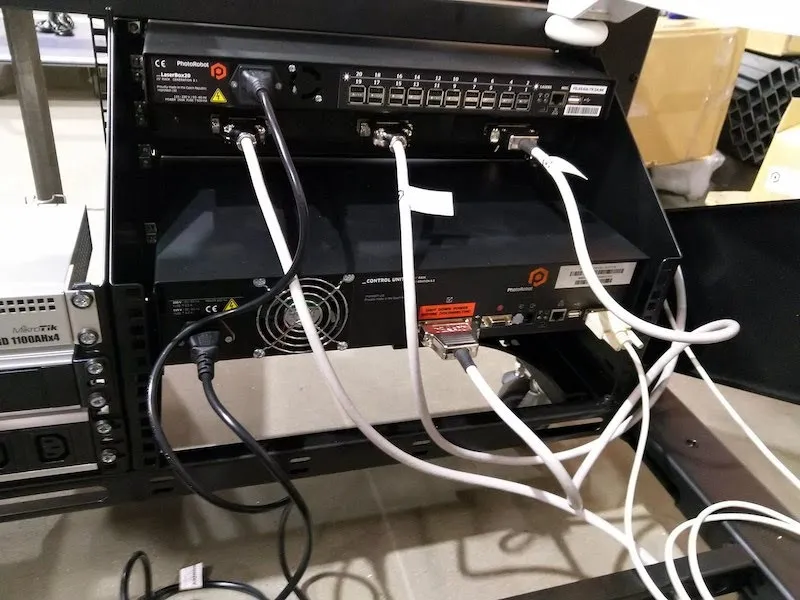
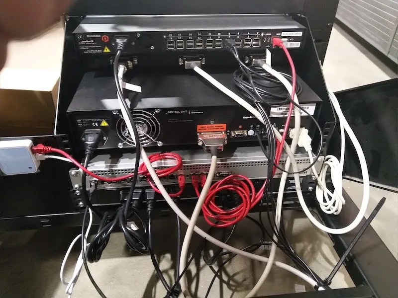
3. إعداد رف HD يساري بدون مركز
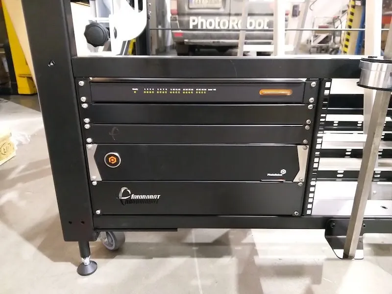
على الجانب الأمامي من الطاولة بدون مركز، يوجد رف عالي الدقة مع رفوف في النصف السفلي الأيسر من إطار الجهاز. يحتوي رف HD على جهاز LaserBox، وSwitchBox، ووحدة التحكم.
3.1. اتجاه رف HD
عند تجميع رف HD، قم بتركيب وحدات التحكم بالترتيب التالي من الرف العلوي إلى السفلي:
- ليزر بوكس (الرف العلوي)،
- سويتشبوكس،
- رف ضيق بمنظار،
- وحدة التحكم،
- رف واسع مع شعار (في الأسفل).
3.2. نظام اتصال أجهزة رف HD
3.2.1. لإعداد الأجهزة في رف HD، ابدأ بتوصيل أول مجموعة من الأسلاك إلى كل وحدة تحكم باستخدام الكابلات التالية.
- كابلات طاقة سوداء بطول متر واحد
- كابل رمادي RS232 بطول متر واحد مع موصل وحدة تحكم G6 (CUG6) إلى CL1300 / CL850 عند الهيكل العظمي
3.2.2. بعد ذلك، حدد موقع كابلات المحرك الرمادية، وربطها كما يلي.
- وحدة التحكم G6 بطول متر واحد (CUG6) إلى موصل SwitchBox الأيمن
- موصل SwitchBox الأوسط بطول متر واحد إلى موصل CL1300 / CL850 عند الهيكل العظمي
- موصل SwitchBox الأيسر بطول 5 أمتار للاتصال لاحقا بموصل البوابة
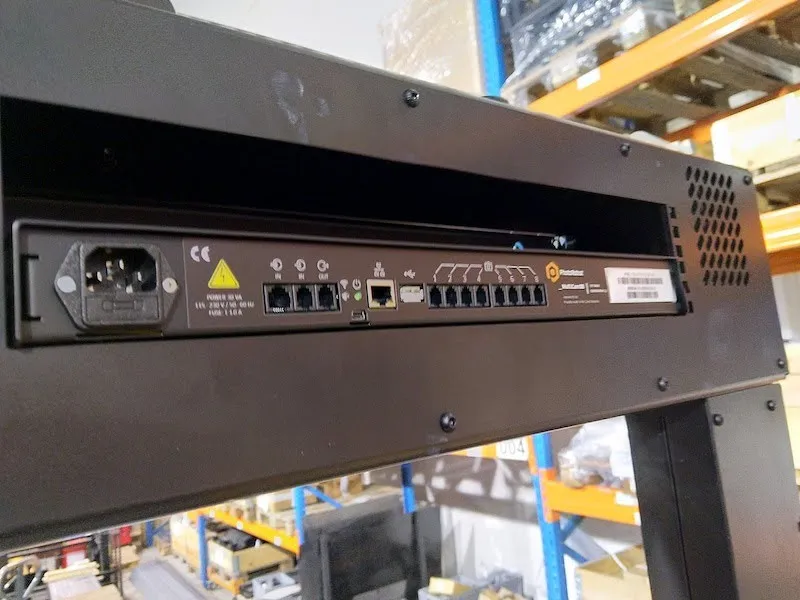
3.3. جهاز التوجيه - نظام توصيل الطاقة
3.3.1. لتوصيل الراوتر إذا لم يكن متصلا بالفعل، قم بتركيبه مع مقابس طاقة متعددة في الرف الأوسط في CL1300. إذا كنت تضبط CL850، قم بتركيب الراوتر مع مقبس الطاقة المتعدد الثاني في الرف الصغير الخلفي للجهاز.
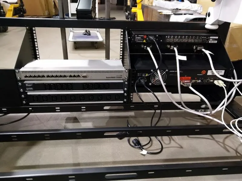
3.3.2. وأخيرا، قم بتوصيل كابلين كهربائيين أسود بقطر متر واحد إلى الجزء الخلفي من الراوتر.
4. تركيب حوامل كاميرات متعددة الكاميرات
بعد إعداد رف HD والراوتر، المرحلة التالية هي تركيب حوامل كاميرا MultiCam على مقدمة MultiCam.
4.1. تركيب حوامل كاميرات متعددة الكاميرات
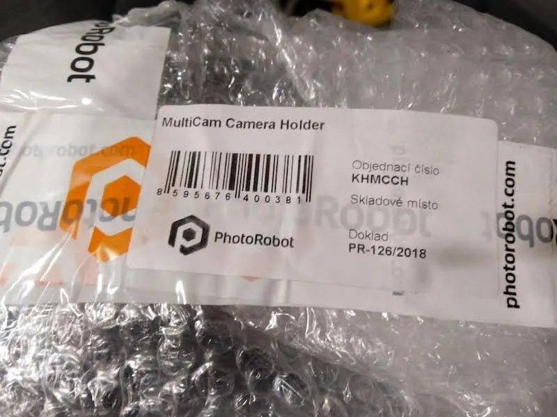
4.1.1. تحديد موقع وفك كل حزمة تحمل علامة MultiCam Camera Camera Holder (الرمز: KHMCCH).
4.1.2. تركيب حوامل الكاميرا في مقدمة الكاميرا المتعددة بالزوايا المطلوبة.
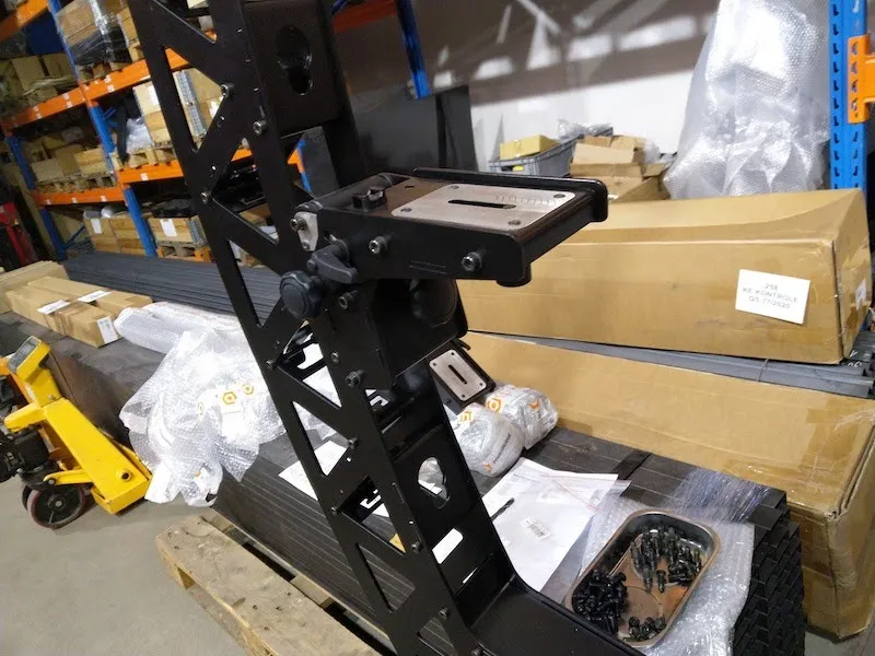
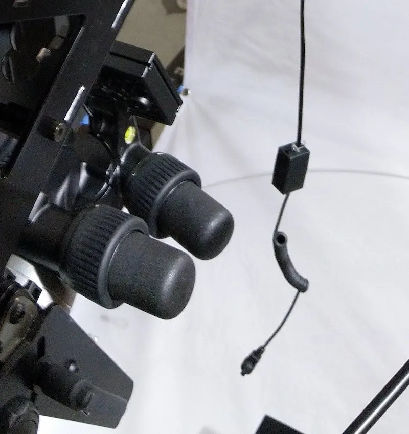
4.1.3. بعد ذلك، حدد موقع رؤوس مانفروتو، وركبها على حوامل الكاميرات.
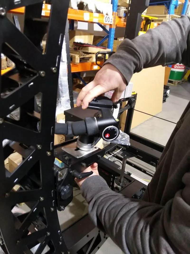
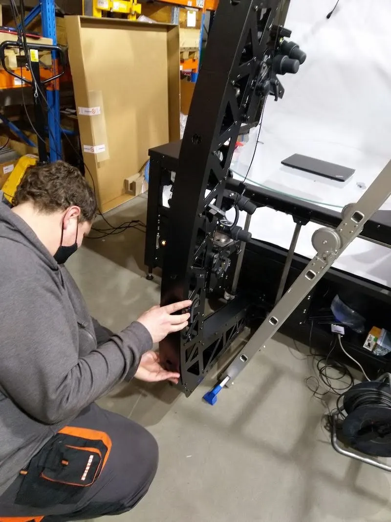
4.1.4. بعد تركيب رؤوس مانفروتو، اكشف عن كلا الصدغين عن طريق فك كل براغي على الأغطية.
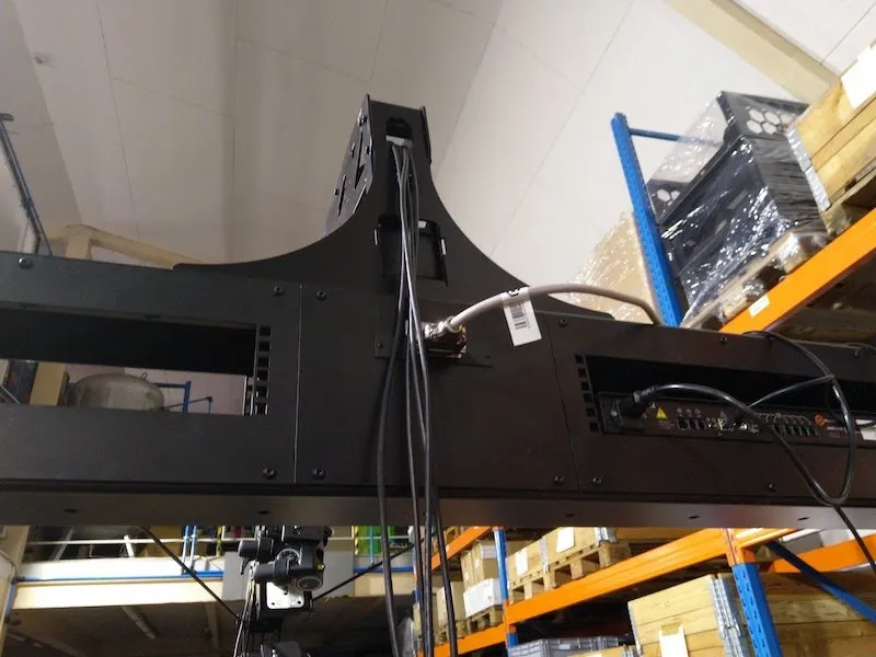
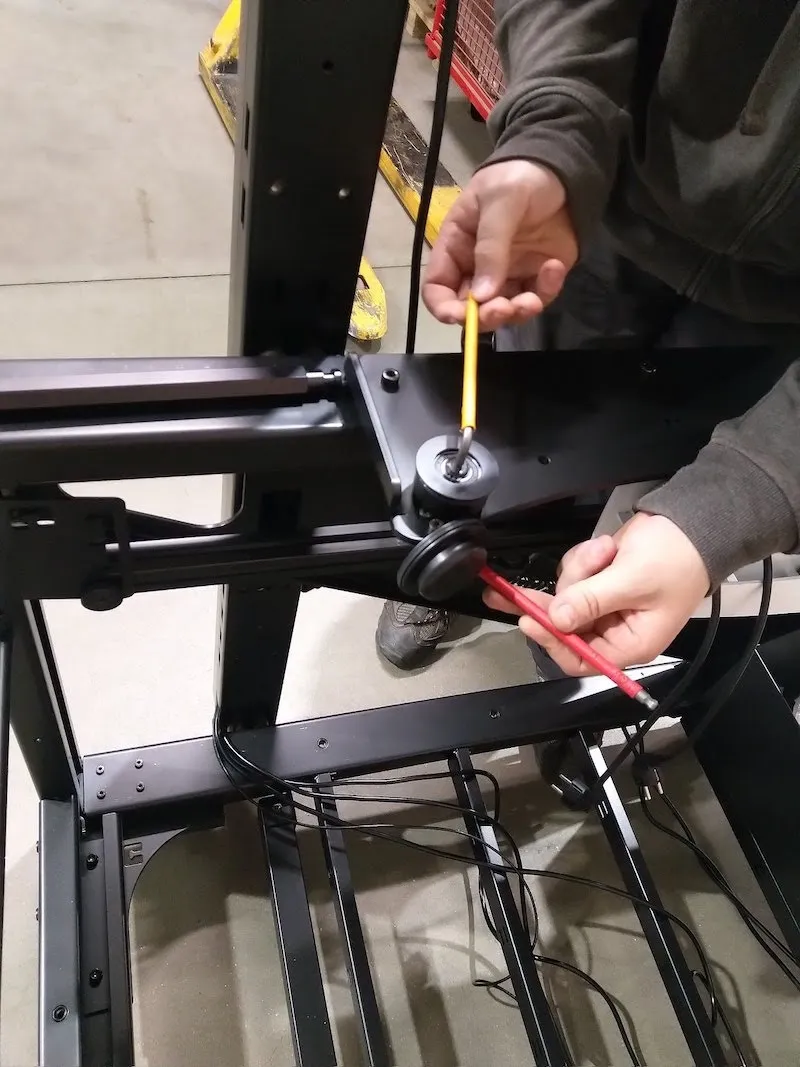
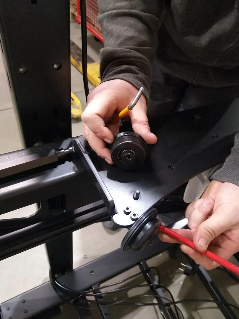
4.2. الهيكل الأيسر واليمنى - توجيه الكابلات الداخلية
4.2.1. وضع الكابلات في الدرجات التالية داخل الأجزاء الداخلية من الصدغ.
4.2.2. في الهيكل الأيسر (من الجانب الأمامي للطاولة بدون مركز)، مرر الكابلات التالية داخليا.
- كابل محرك واحد بطول 5 أمتار، متصل من موصل SwitchBox الأيسر ومثبت بموصل البوابة
- امتداد كابل غالق واحد بطول 5 أمتار متصل من منفذ CUG6 OUT إلى منفذ SynchroBox IN (المنفذ الأصغر)
- 4 × موسعات USB نشطة 10 أمتار
- 3 أسلاك طاقة سوداء 5 أمتار للمصابيح اليدوية وSynchroBox
- كابل إيثرنت واحد بطول 5 أمتار لجهاز SynchroBox
- 1 × موسع USB أسود بسيط للليزر الأوسط
4.2.3. لتركيب الكابلات داخل الهيكل الأيمن (من الجانب الأمامي للطاولة بدون مركز)، جهز الكابلات التالية.
- 3 أسلاك طاقة سوداء 5 أمتار للمصابيح اليدوية
- 1 × موسع USB أسود بسيط للليزر الجانبي
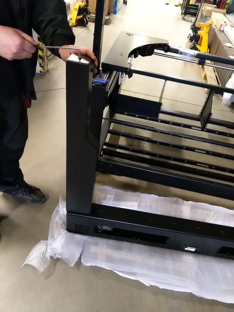
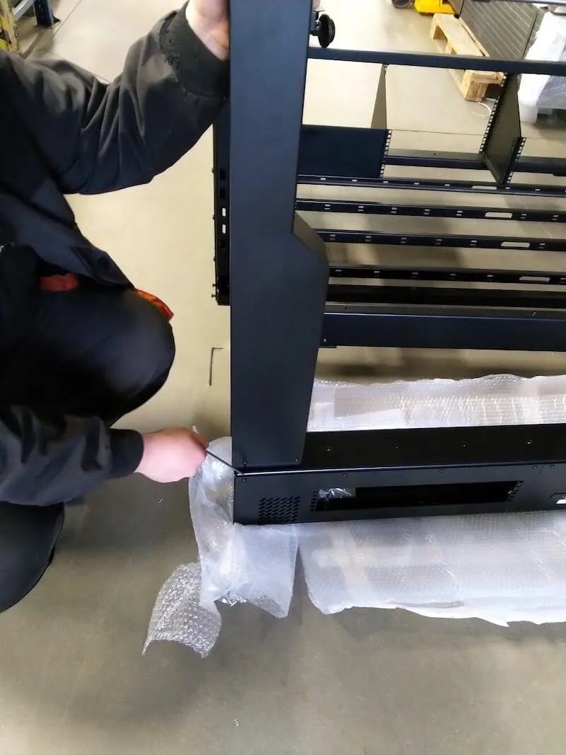
4.2.4. بعد ذلك، ابحث عن اثنين من الطبقات المعبأة في غلاف الفقاعات ومكتوب عليها زوج من الطبقات الجانبية النوع H (الرمز: KHANYTH)، وفك كل منهما.
4.2.5. ضع غطاء الصدغ فوق الجزء المقوى من الصوغة، وأدخل مسمار واحد عبر كلا القطعتين.
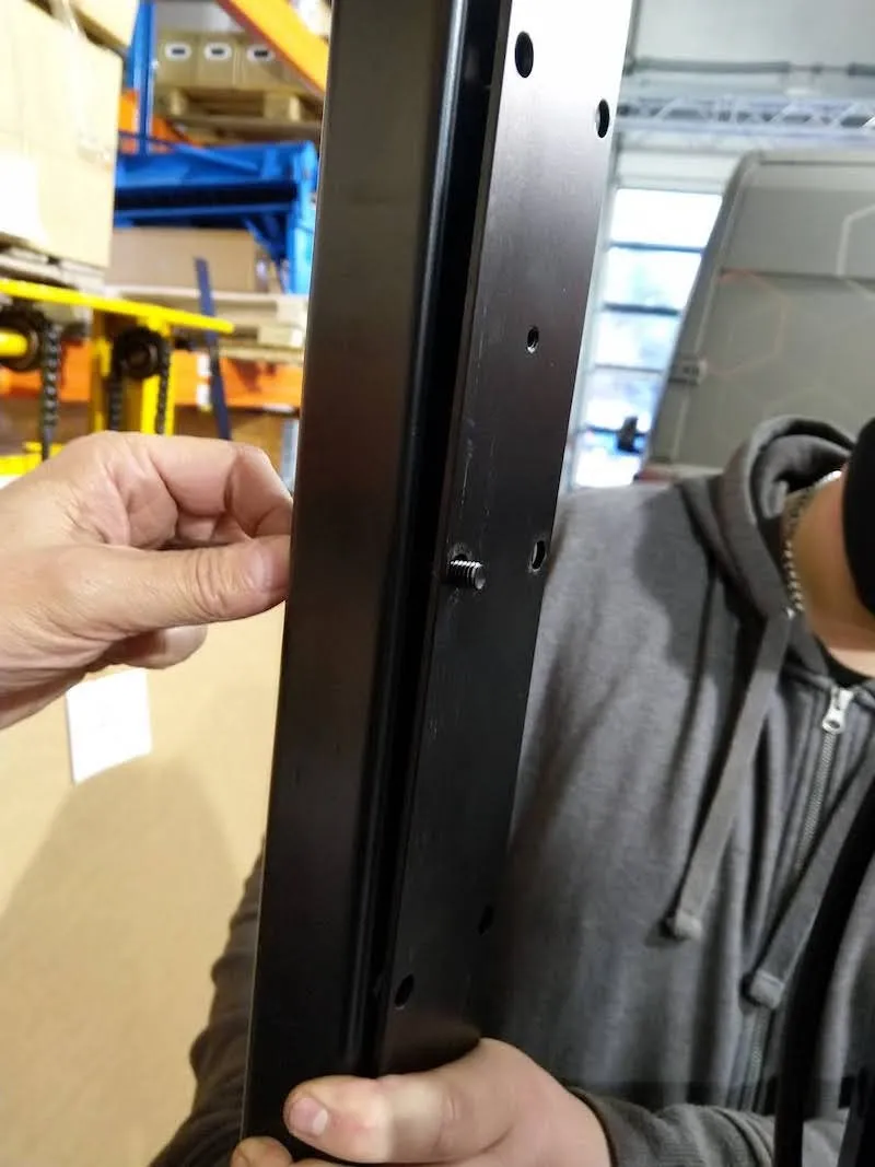
4.2.6. ربط الجزأين لتثبيت الصدغين على الطاولة بدون مركز.
4.2.7. إدخال وشد جميع البراغي المتبقية على الصدغ باستثناء الأربعة البراغي العلوية (صفان) في كلا الصدغين.
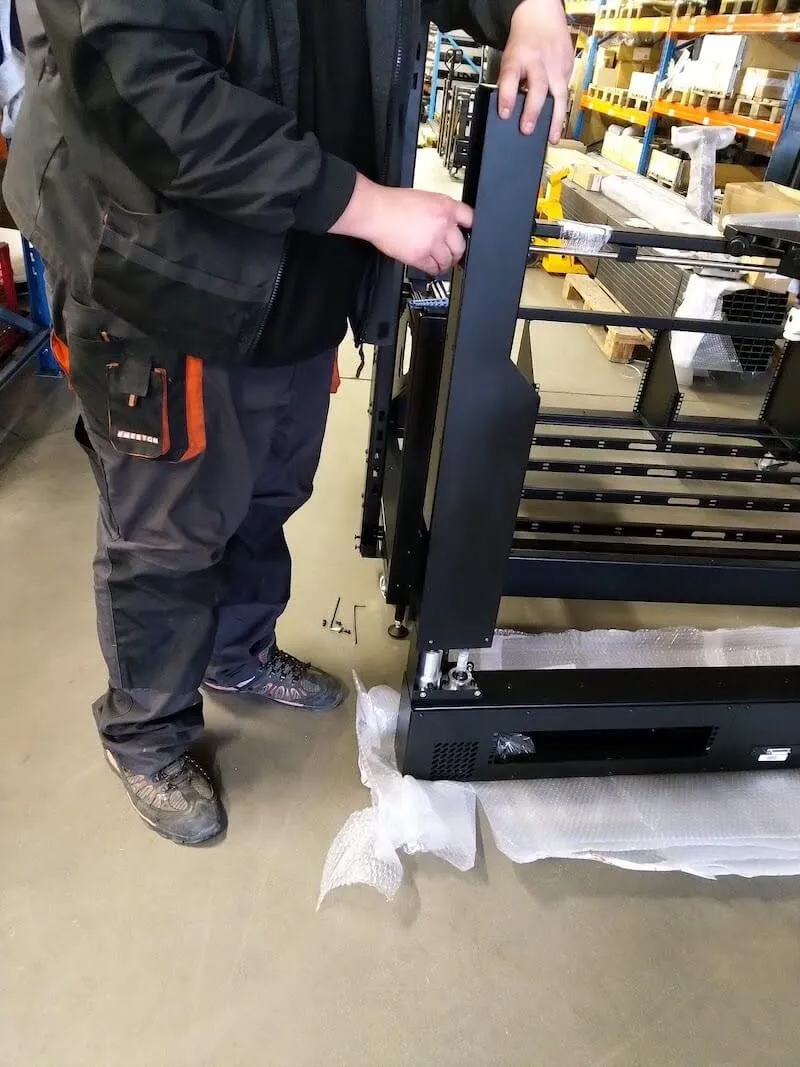
4.2.8. اتبع نفس الخطوات على المعبد الآخر.
4.2.9. إدخال موسعات USB النشطة في القوس، ثم ضبط موضع كل موسع نشط USB لكل رأس مانفروتو.
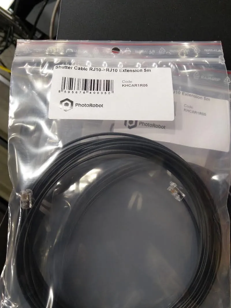
4.3. التوجيه الداخلي لامتداد كابل الغالق
4.3.1. أخيرا، حدد 4 كابلات تمديد لكابل الغالق في كيس بلاستيكي بلاستيكي معنون باسم Shutter Cable RJ10 إلى RJ10 Extension 5m (الرمز: KHCAR1R05).
4.3.2. إدخال امتدادات كابل الغالق في المقدمة وضبط موضع كل امتداد لكل رأس مانفروتو. ملاحظة: يجب أن يتصل الجانب الآخر من كابلات الغالق بجهاز SynchroBox، بينما يتصل كابل مصراع رأس مانفروتو الأدنى بمنفذ SynchroBox، المنفذ 1. وفي الوقت نفسه، يتصل كابل غالق رأس مانفروتو العلوي بجهاز SynchroBox، المنفذ 4.
5. تجميع وحدة تحكم حامل خلفية CL1300 / CL850
بعد ذلك، هناك تجميع وحدة تحكم حاملة الخلفية للطاولة بدون مركز.
5.1. تجميع وحدة تحكم حامل الخلفية
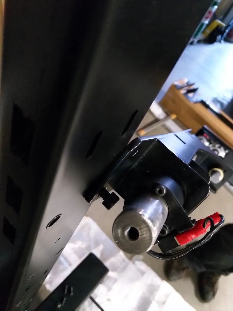
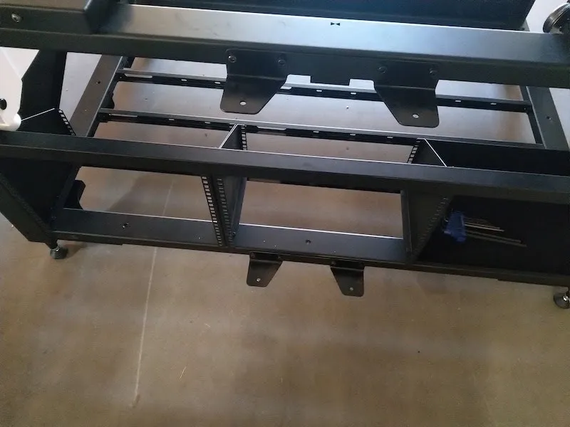
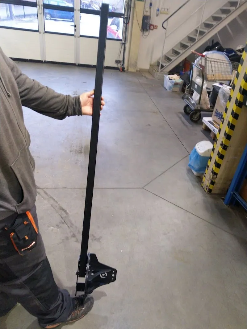
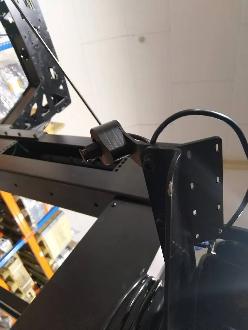
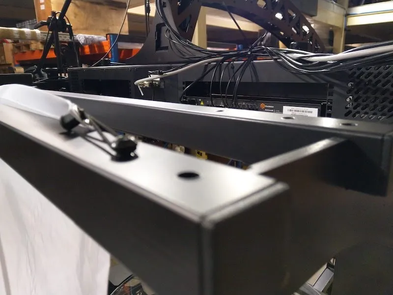
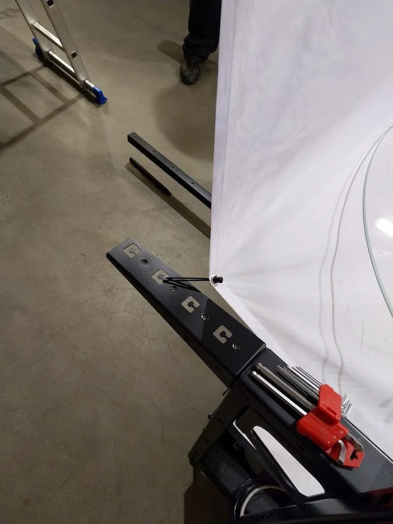
5.1.1. تحديد موقع وحدة تحكم حامل الخلفية، كما هو موضح أدناه.
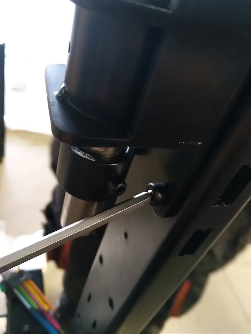
5.1.2. ربط حامل الخلفية بالصدغين الأيسر والأيمن.
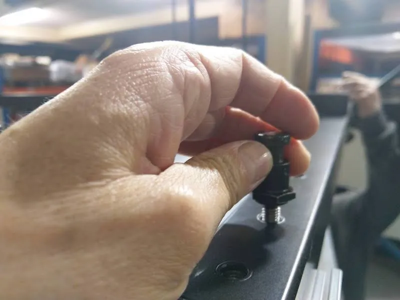
5.1.3. تأكد من تثبيت حامل الخلفية بقوة في الفتحات. ثم قم بفك براغي القفل ذات الرؤوس البلاستيكية، وأدخل دبوس الأمان المعدني قدر الإمكان في فتحة الصدغ. بعد ذلك، شد براغي القفل برؤوس بلاستيكية لتثبيت الخلفية.
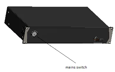
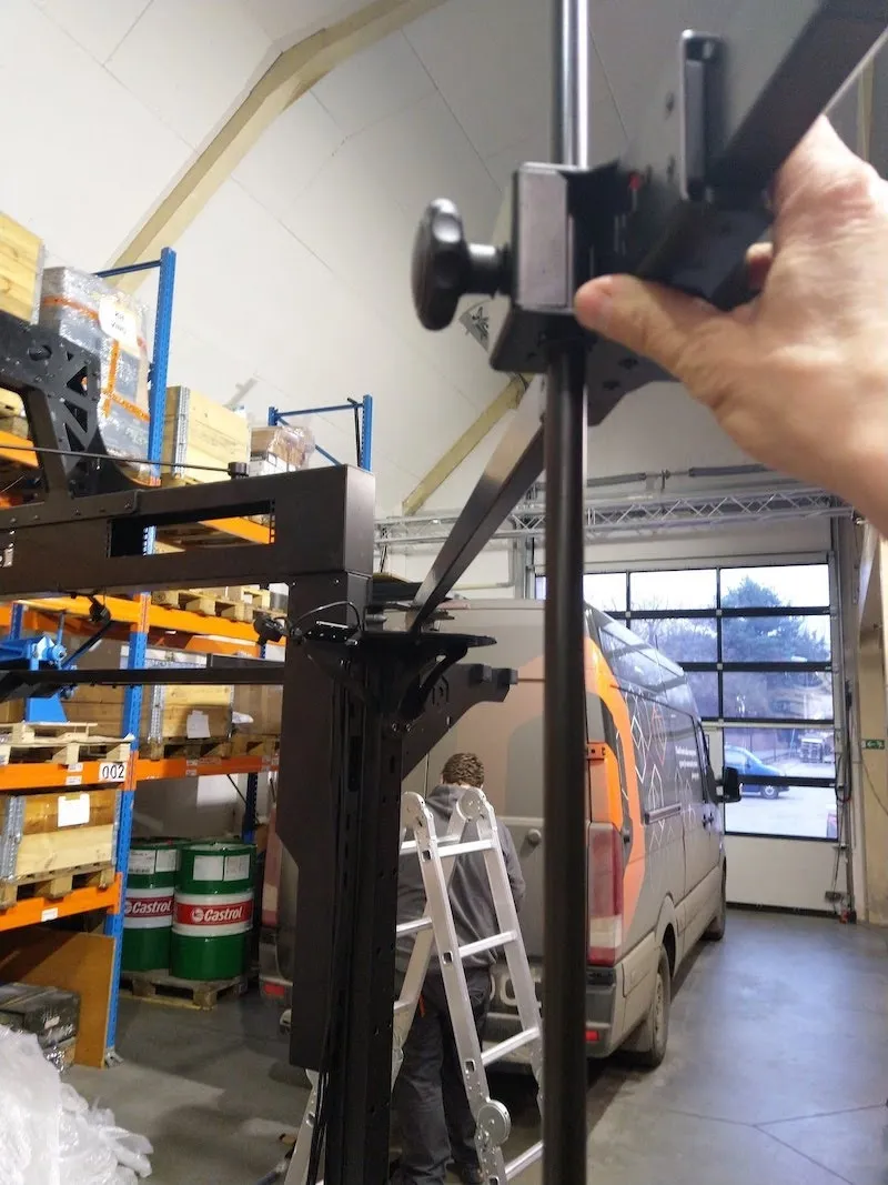
5.2. إيقاف حركة المفتاح في نهاية الاختبار
بعد تأمين وحدة تحكم حامل الخلفية، شغل وحدة التحكم (مؤقتا، حسب الحاجة)، وانقل البوابة إلى الموقع العلوي. يجب أن يوقف مفتاح النهاية الحركة.
6. مجموعة حوامل المصابيح اليدوية
بعد بناء حامل الخلفية، المرحلة التالية هي تجهيز مجموعة حوامل المصباح اليدوي.
6.1. تركيب هيدجهوج (حاملات أضواء الطيران)
6.1.1. تحديد موقع الصندوق الذي يحتوي على حوامل المصابيح اليدوية الملفوفة بالبلاستيك، وفك الأجزاء.
6.1.2. بعد ذلك، جهز القنافذ (حاملات المصابيح) للتجميع.
6.2. مجموعة حامل الليزر
6.2.1. تحديد موقع حامل الليزر الجانبي (المثلث)، وربطه مع القنفذ على الهيكل المعزز على الجانب الأيمن. يجب أن يكون الترتيب: صخرة، تليها حاملة ليزر، وأخيرا قنفذ.
6.2.2. كرر نفس العملية على الصدغ الآخر، وهو بدون حامل الليزر.
6.2.3. ثبت كلا الليزرين ووصلهما بموسعات USB السوداء البسيطة الموجودة بالفعل.
6.3. تركيب الأضواء اليدوية
6.3.1. لتركيب الأضواء، قم بفك براغي الأمان في كلا حامل المصابيح اليدوية.
6.3.2. بعد ذلك، أدخل القضبان لتركيب المصابيح اليدوية، مع مراعاة اتجاه الشعار واستبدال برغي الأمان بعد ذلك.
6.3.3. تركيب حامل الضوء الخلفي العلوي.
6.3.4. فك وأزل برغي الأمان.
6.3.5. إدخال القضيب لتركيب المصباح اليدوي، واستبدال برغي الأمان.
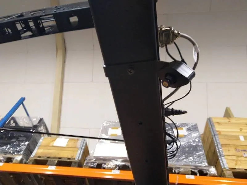
6.3.6. ثبت حامل المصباح الخلفي السفلي كما في الصور التالية.
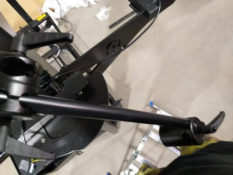
6.4. تركيب ذراع حائط حامل الإضاءة العلوية
6.4.1. ابحث عن أجزاء حامل الإضاءة العلوي (ذراع الحائط).
6.4.2. وضع أنبوب الفاصل بنفس الطريقة كما في الصورة التالية.
6.4.3. أدخل البرغي، ثم ثبت القرن.
6.4.4. بعد ذلك، أدخل حامل ذراع الحائط.
6.4.5. إدخال ذراع الحائط، ثم تثبيت الوزن في نهايته.
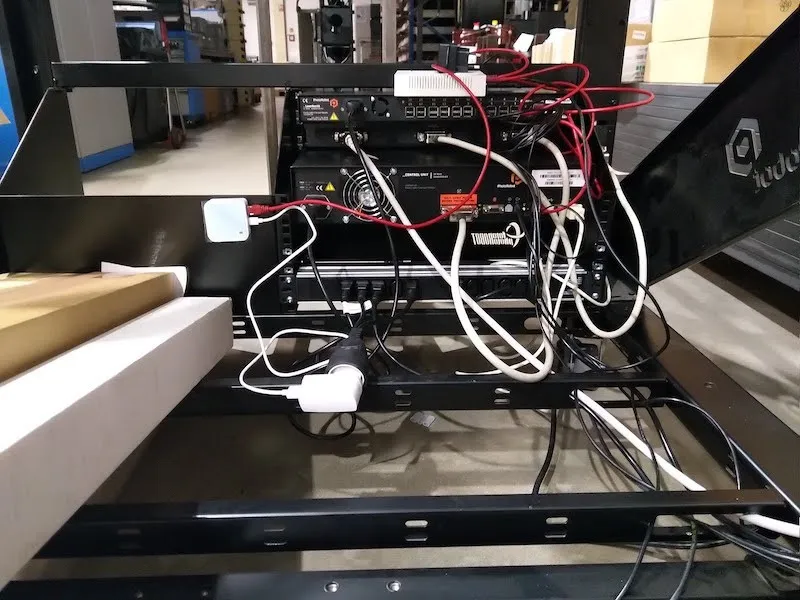
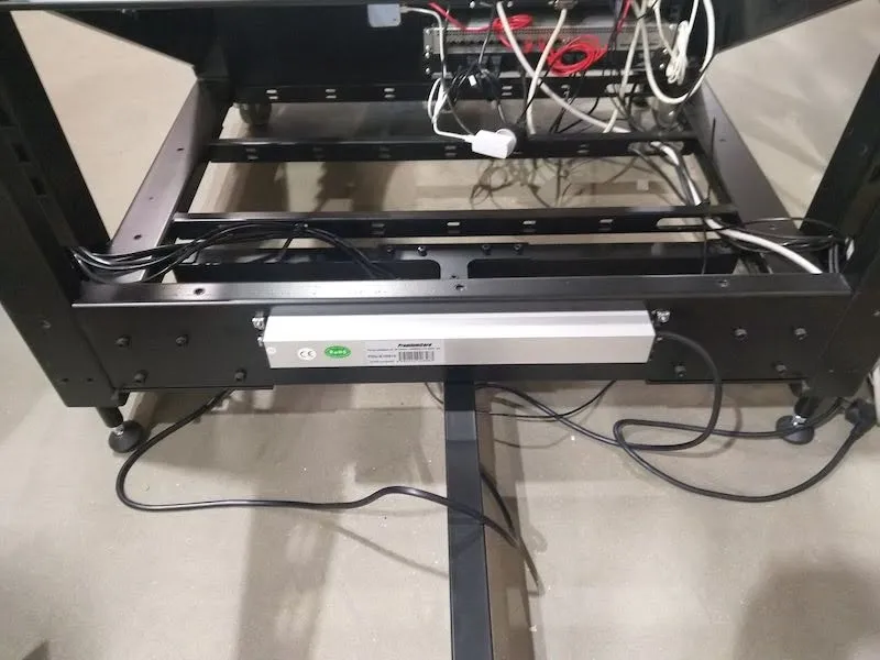
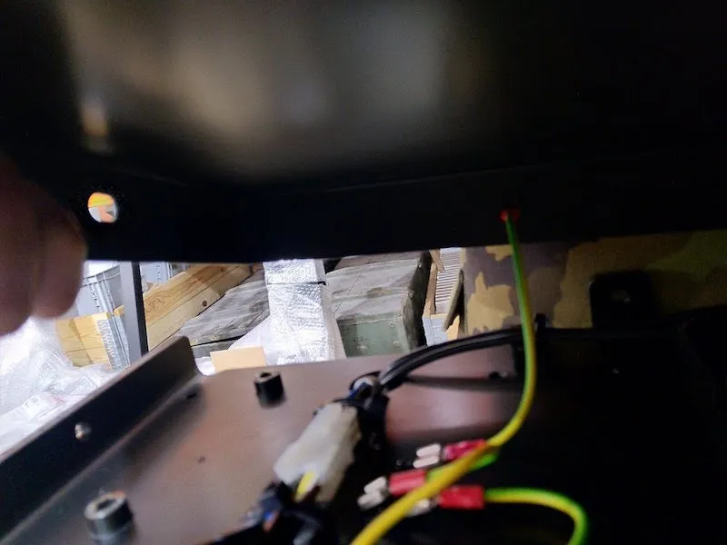
6.5. نظام توصيل الكابل
6.5.1. أخيرا، وصل الكابلات المتبقية بجميع الأجهزة، ورتب الكابلات في الأسفل، واستخدم أربطة الكابلات لربط الكابلات معا.
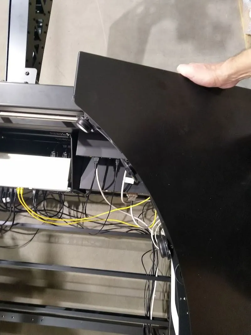
6.5.2. انتبه لتكوين الراوتر (المنفذ 1 - 12 = LAN، المنفذ 13 = الإنترنت). ثم قم بفك وفتح غطاءين علويين فوق عجلات توجيه اللوحة.
6.5.3. تذكر فصل أسلاك التأريض.
7. تركيب الألواح لجهاز CL1300 / CL850
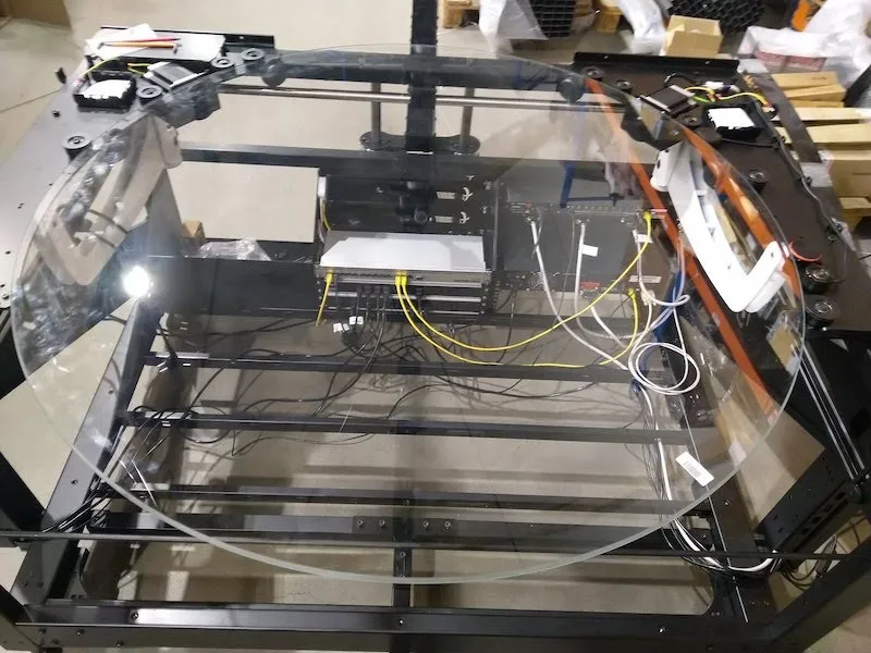
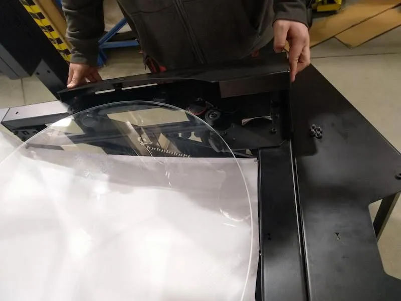
7.1. بعد ذلك، استعد لتركيب لوحة الطاولة بدون مركز عن طريق فك وإزالة عجلة خلفية واحدة، باستخدام الصور التالية كإرشاد.
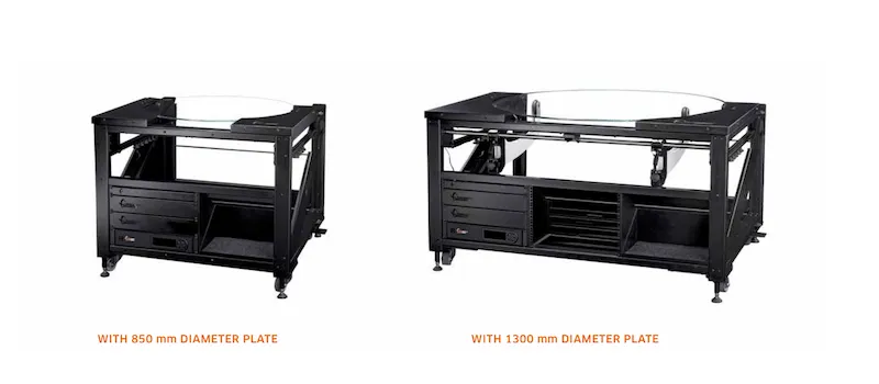
7.2. تحديد موقع اللوحة الزجاجية (1300 مم ل CL1300، أو 850 مم ل CL850).
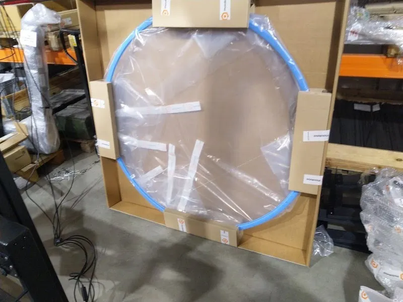
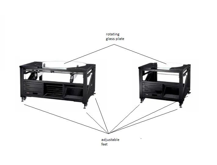
7.3. ضع اللوحة الزجاجية بعناية على العجلات الداعمة، مع التأكد من أن الشق في اللوحة الزجاجية موجه للأسفل.
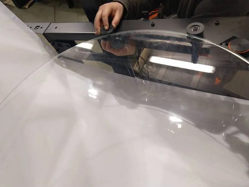
7.4. أعد وثبت العجلة التي أزيلت ثم أعدها إلى الوضع.
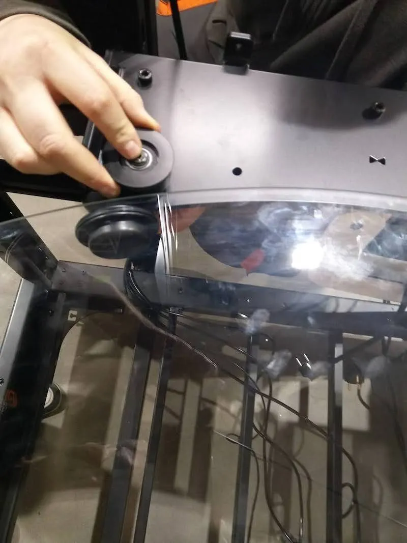
7.5. ضبط العجلة الجانبية بحلقات مطاطية، مع التأكد من ملامسة الحلقات للزجاج. ملاحظة: الضغط الصحيح يسمح بتثبيت وإيقاف كل عجلة يدويا عندما يدور الزجاج.
7.6. ضع الغطاءين العلويين لعجلات التوجيه الزجاجية إلى الخلف وشد البراغي.
8. تجميع خلفية ل CL1300 / CL850
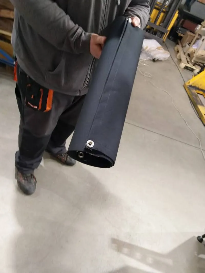
8.1. لبناء مجموعة الخلفية، حدد الخلفية البيضاء للطاولة بدون مركز.
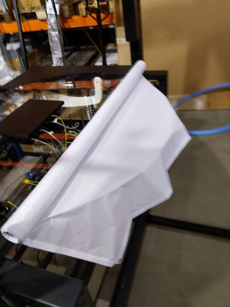
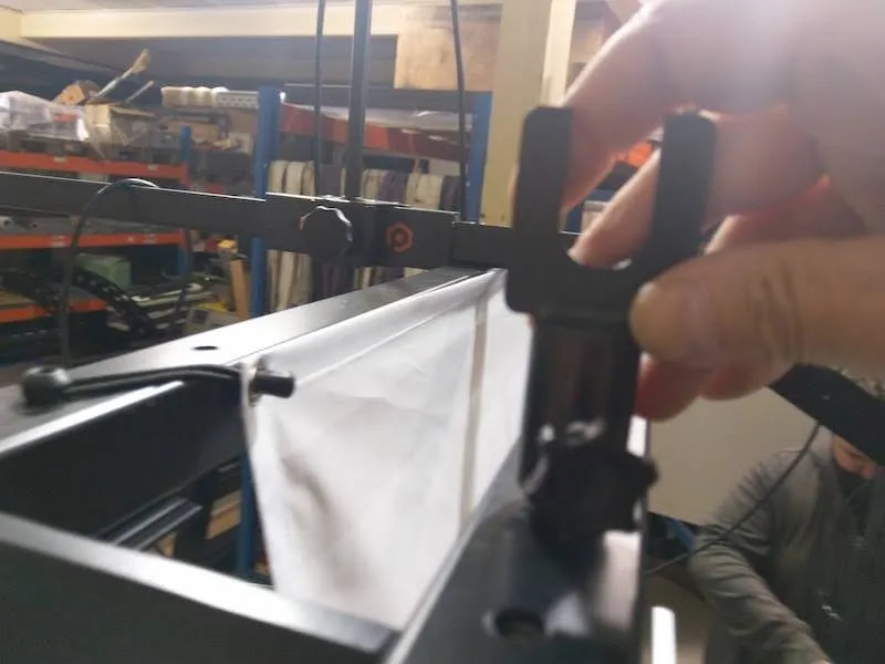
8.2. بعد ذلك، جهز المشابك المطاطية للخلفية.
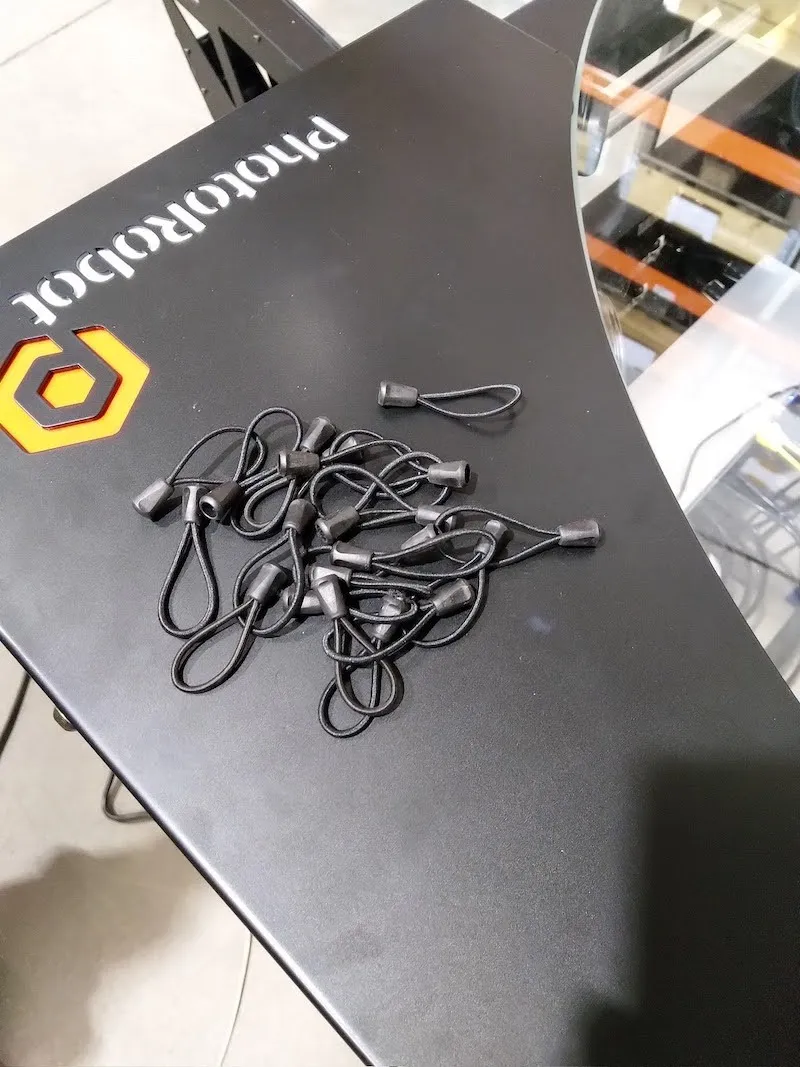
8.3. تأمين الخلفية عن طريق تثبيت المشابك المطاطية على وحدة تحكم حامل الخلفية.
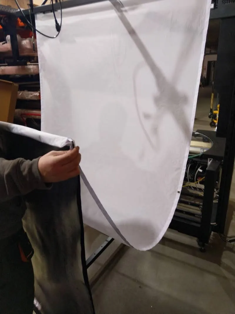
8.4. حرك الخلفية البيضاء إلى الموضع النهائي، وتثبيتها باستخدام المشابك المطاطية.
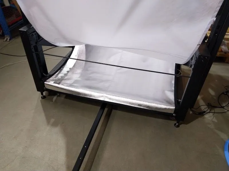
8.5. أعد حوامل الخلفية، ثم أعيدها إلى مكانها.
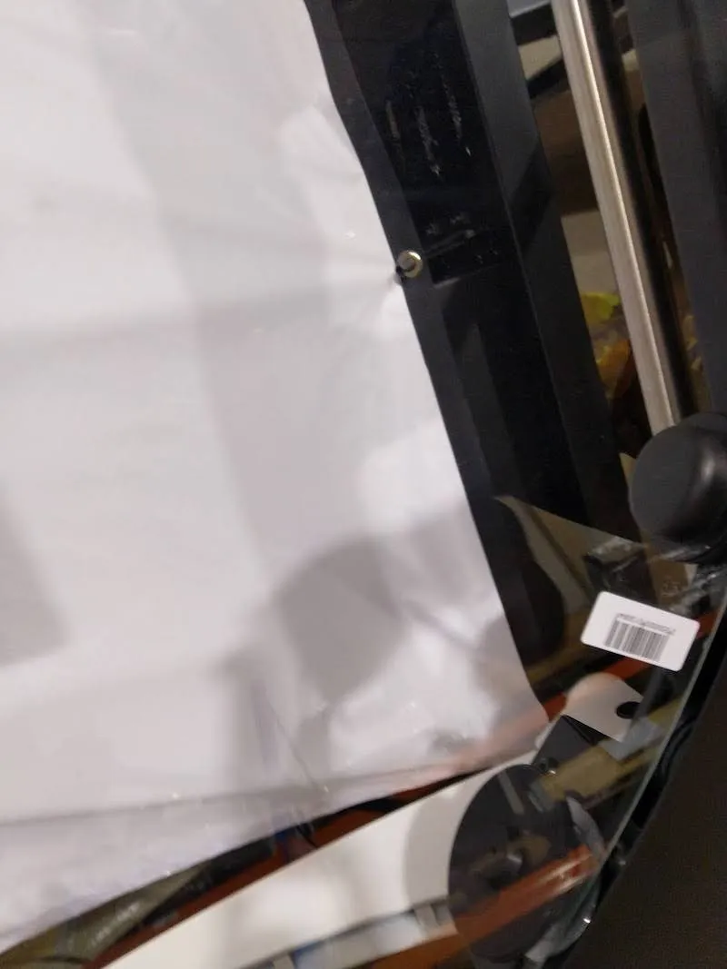
8.6. بعد ذلك، إذا كنت تجمع CL1300، حدد موقع الأغطية الجانبية وافتح كل واحدة. إذا كنت تقوم بتجميع CL850، لاحظ أن الجهاز لا يحتوي على أغطية جانبية، وتابع الخطوة 8.9.
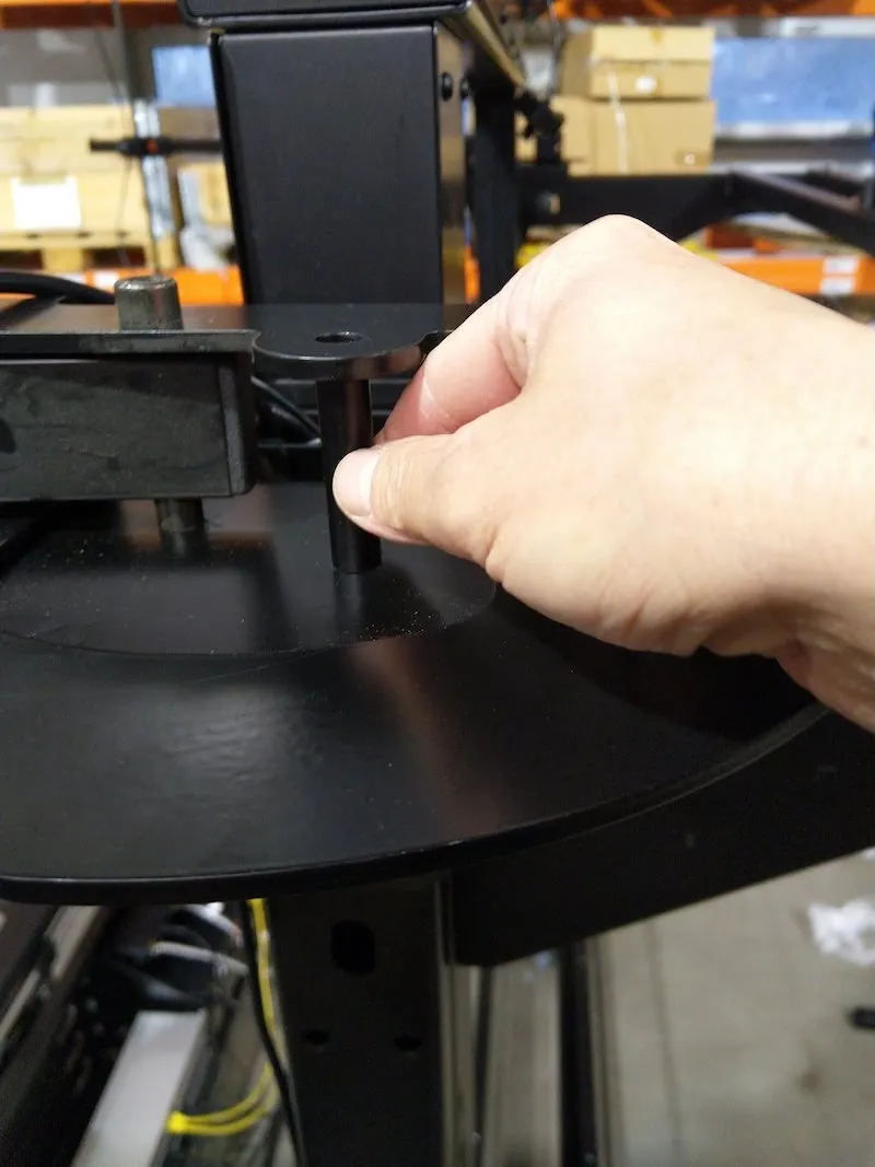
8.7. ثبت الأغطية الجانبية على الجانبين الأيمن والأيسر من الطاولة بدون مركز.
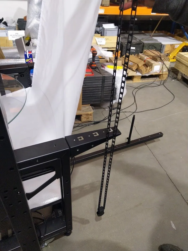
8.8. أدخل دبوسين x في وحدة تحكم حامل الخلفية، وثبت الدبابيس في مكانها.
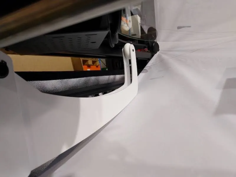
8.9. بعد ذلك، أدخل شوكات فوق الدبابيس، وثبتها في مكانها.
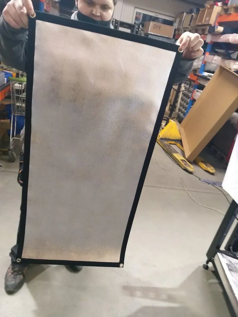
8.10. حدد الخلفية السوداء وضعها في الشوكات.
8.11. جهز السلسلة البلاستيكية التي تتحكم في الخلفية السوداء الساخرة.
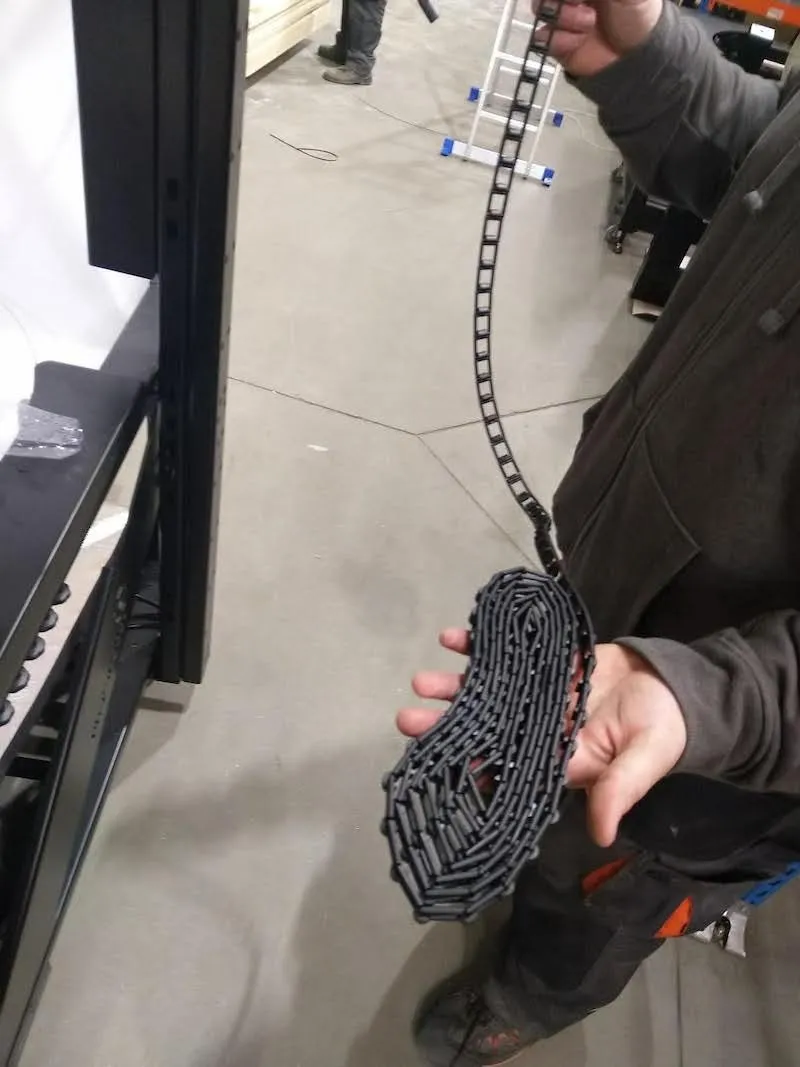
8.12. ضع السلسلة على الترس في الصورة التالية.
8.13. الآن، أضف الوزن إلى السلسلة، واربط السلسلة معا.
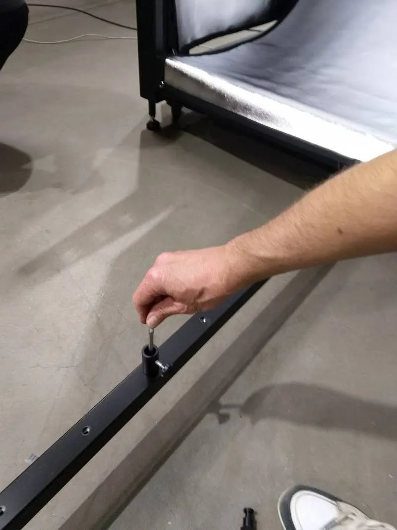
8.14. تركيب المقبس وقضيب حامل المصباح في الخلفية السفلية.
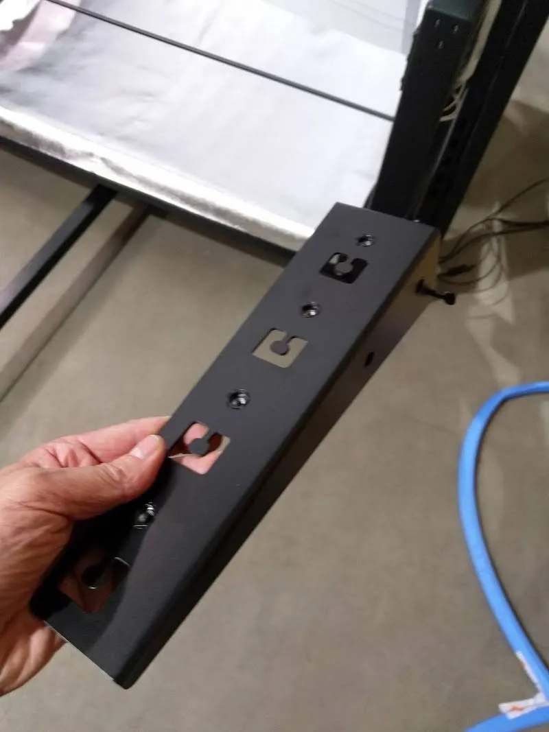
9. تركيب أغطية معدنية للقوس متعددة الكامات (CL1300)
9.1. بعد ذلك، إذا كنت تجمع الكاميرا المتعددة مع CL1300، قم بتجهيز الأغطية المعدنية لقوس MultiCam للتركيب. ملاحظة: بالنسبة ل CL850، لا توجد أغطية معدنية، لذا تابع الخطوة 9.3.
9.2. وضع الأغطية بين الأقفال، مع تثبيت الأغطية بواسطة مغناطيسات بعد ذلك.
9.3. توصيل الطرفين بموصل إلى امتداد كابل الغالق الأقرب لكل رأس مانفروتو.
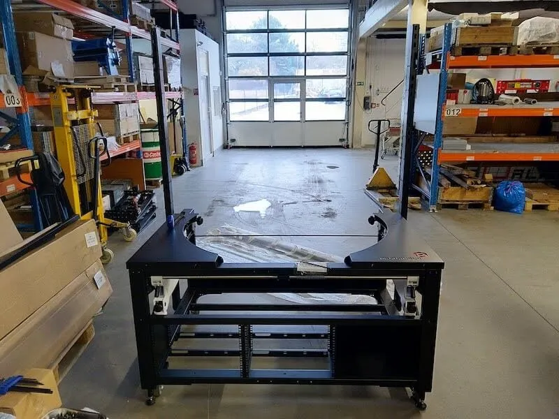
9.4. الكاميرا المتعددة مع الطاولة بدون مركز (CL1300 / CL850) جاهزة للاستخدام.
10. الاستخدام الأول والاختبار الأساسي
لمزيد من الدعم بعد تركيب الكاميرا المتعددة مع الطاولة بدون مركز، راجع PhotoRobot First Use & Basic Test.
11. PhotoRobot _Controls برمجيات
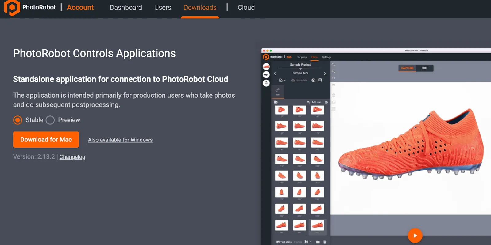
يوفر تطبيق PhotoRobot Controls ("CAPP") تحكما كاملا في محطة العمل MultiCam مع الطاولة بدون مركز (CL1300 / CL850)، وأجهزة PhotoRobot الأخرى. يدمج CAPP التحكم في الروبوتات والكاميرات وأضواء الاستوديو وما بعد الإنتاج. يشمل ذلك ميزات إدارة سير العمل بالإضافة إلى الوظائف اللازمة لأتمتة فعالة في المعالجة اللاحقة.
ملاحظة: برنامج تطبيق PhotoRobot Controls لا يتم تسليمه مع الجهاز؛ بل هو شراء منفصل متاح للتحميل عبر حساب PhotoRobot الخاص بك.
للدعم في التركيب والبدء، راجع Getting Started - PhotoRobot Controls.
علاوة على ذلك، قد يبدأ البرنامج في "وضع الساحر" بعد تثبيت CAPP. وضع الساحر هو واجهة مستخدم مبسطة تتيح مسح الرموز الشريطية لتحديد الكائنات وبدء تسلسلات الالتقاط تلقائيا. لمزيد من المعلومات حول وضع الساحر، يرجى الرجوع إلى إعدادات وضع الساحر في تطبيق PhotoRobot Controls.


سلسلة EOS Rebel


سلسلة EOS DSLR


سلسلة EOS M عديمة المرآة


سلسلة PowerShot


لقطة مقربة / محمولة باليد

توفر سلسلة EOS Rebel من Canon كاميرات DSLR سهلة الاستخدام للمبتدئين بجودة صورة قوية وعناصر تحكم بديهية وميزات متعددة الاستخدامات. مثالية لعشاق التصوير الفوتوغرافي ، توفر هذه الكاميرات تركيزا بؤريا تلقائيا موثوقا به وشاشات لمس متغيرة الزوايا وتسجيل فيديو عالي الدقة أو 4K.
اتصال
القرار (MP)
دقة
توفر سلسلة EOS DSLR من Canon صورا عالية الجودة وتركيزا بؤريا تلقائيا سريعا وتعدد الاستخدامات، مما يجعلها مثالية لكل من التصوير الفوتوغرافي وإنتاج الفيديو.
اتصال
القرار (MP)
دقة
تجمع سلسلة EOS M Mirrorless Series من Canon بين التصميم صغير الحجم والأداء الشبيه بكاميرا DSLR. تتميز هذه الكاميرات بعدسات قابلة للتبديل وضبط تلقائي للصورة سريع ومستشعرات صور عالية الجودة ، وهي رائعة للمسافرين ومنشئي المحتوى الذين يبحثون عن قابلية النقل دون التضحية بجودة الصورة.
اتصال
القرار (MP)
دقة
توفر الفئة PowerShot Series من Canon كاميرات صغيرة الحجم وسهلة الاستخدام للرماة العاديين والمتحمسين. مع الطرز التي تتراوح من كاميرات التأشير والتصوير البسيطة إلى كاميرات التكبير المتقدمة ، فإنها توفر الراحة وجودة الصورة القوية وميزات مثل تثبيت الصورة والفيديو بدقة 4K.
اتصال
القرار (MP)
دقة
تم تصميم الكاميرات المقربة والمحمولة باليد من Canon للتصوير الفوتوغرافي والفيديو التفصيلي عن قرب. فهي صغيرة الحجم وسهلة الاستخدام ، وتوفر تركيزا دقيقا وتصويرا عالي الدقة وإمكانيات ماكرو متعددة الاستخدامات - مثالية لمدونات الفيديو وتصوير المنتجات واللقطات المقربة الإبداعية.
اتصال
القرار (MP)
دقة


